Carson Kelley
Progress Report
Week 2
Due Date: 8-30-19
Total hours: 7 hours
Description of design efforts:
For this week my main goal was to better determine the components we would need to use in the design of our electronic dice. In the pursuit of this goal I have determined the microcontroller that we will likely use is the SPBTLE-1S due to its built in Bluetooth module and size. Another consideration was the ability to communicate with an IMU, which through some preliminary research seem to mostly use either SPI or I2C. These are both interfaces included on the SPBTLE-1S. I also investigated the power requirements of the dice and how to charge them. Using wireless charging or external charge ports seem like our two best options, but we have not made a final decision.
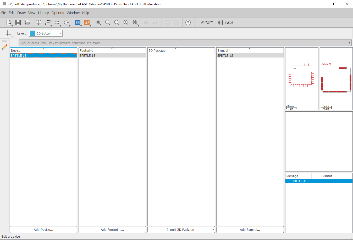
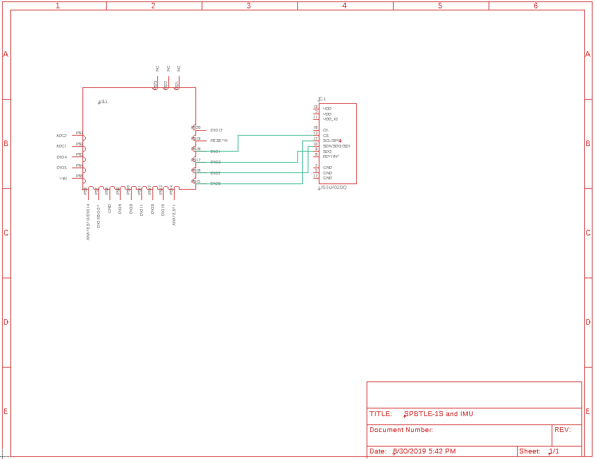
In following this up I went through the EAGLE PCB tutorial provided and designed a library containing the SPBTLE-1S chip. I then made a simple diagram connecting it to an accelerometer chip I found in EAGLE just for practice. This was to refresh my knowledge of EAGLE, especially over how to create new parts/libraries. This will be important for the project because I will be the person in charge of designing our PCB’s. The next step for this is figuring out the actual IMU we want to use in the dice and creating the part in EAGLE. Along with this we will need to decide on our desired method for powering the dice and recharging them.
Week 3
Due Date: 9-6-2019
Total hours: 7 hours
Description of design efforts:
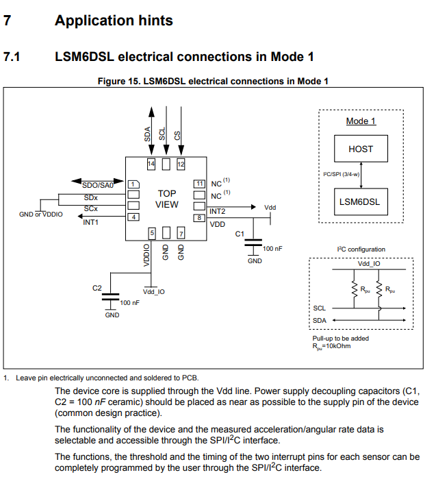
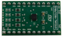
This week my major contribution was finalizing our part selection for the IMU we plan to use in the dice and ordering a breakout board for it so we can begin to prototype with it next week. We selected the ST LSM6DSLTR (https://www.digikey.com/product-detail/en/stmicroelectronics/LSM6DSLTR/497-16705-1-ND/6192805) which is a very low power IMU that has programmable interrupts. These can be used to set it into a super low power sleep state that it will remain in until it detects motion. The breakout board we ordered is the STEVAL-MKI178V2 (https://www.mouser.com/ProductDetail/?qs=lYGu3FyN48fC%2F0yLpJsQFw%3D%3D) which has all of the built components needed to begin prototyping. I also contributed to the component analysis document, mainly with the section on the IMU's which was my main task for the week. This took a lot of time due to the need to keep the power consumption as low as possible since the dice are going to be powered by as small a battery as we can possibly use. This took a lot longer than expected but now that we have ordered our breakout board we will be able to begin prototyping the main dice circuitry in week 4. The next major steps for developing the dice design are to select wireless charging coils to receive and transmit power. My main goal is to finalize a dice design as early as possible and worry about the PCB for the main game board afterwards due to its complexity.
Week 4
Due Date: 9-13-2019
Total hours: 5 hours
Description of design efforts:
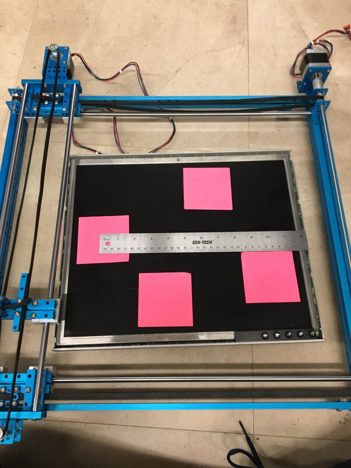
My main contributions for this week was finalizing a Bluetooth module for the main game board and helping with figuring out the main board layout. We had some concerns over fitting the screen in the main game board and had to do some measurements and determined the plotter would be over the display and could be seen by the user. For selecting the Bluetooth we went with the RN4020 and will be prototyping with it next week.
Week 5
Due Date: 9-20-19
Total hours: 10 hours
Description of design efforts:
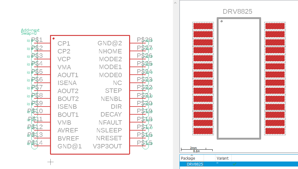
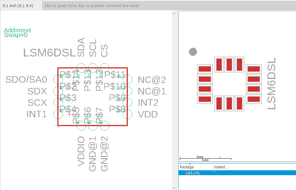
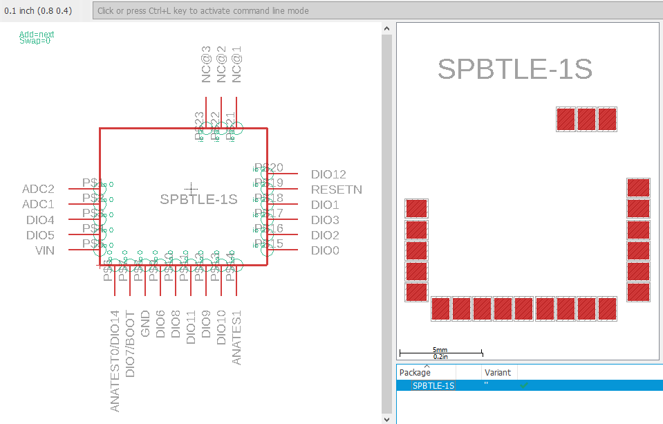
My main design effort has been designing more parts in EAGLE for use in our PCBs. This week I remade my die microcontroller (SPBTLE-1S) part which had some errors. This was due to not knowing the grid in EAGLE could be changed from mils to millimeters. This made it much easier since the datasheet gives the specifications in metric. I also created parts for our IMU (LSM6DSL) and the stepper motor controller (DRV8825) in EAGLE. The only non-passive device left to design for the die’s main PCB is the voltage regulator which will convert 3.6V from our battery into 1.8V to power the die microcontroller and IMU. Through talking with course staff, I learned about drawing coils in EAGLE and how to use this to interface with a Qi charging mat for wirelessly charging our dice. My next step for the PCB is to design the parts for the Qi charging and to then make the parts for the main game board PCB.
Week 6
Due Date: 9-27-2019
Total hours: 10 hours
Description of design efforts:
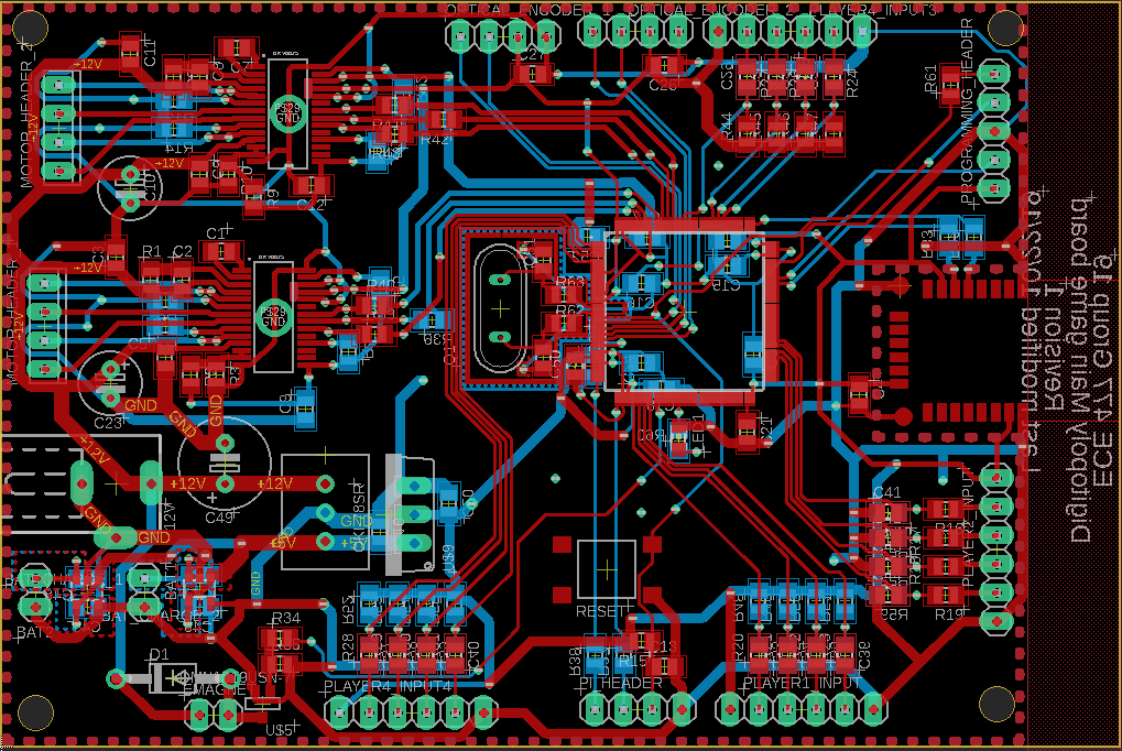
My main effort this week was finishing up designing the parts required for the PCBs in EAGLE. I also had to choose a voltage regulator for the dice which will drop the voltage output from the battery to 1.875V because the microcontroller and IMU, which are the main components on the board, can both operate at this voltage which will reduce our power consumption. This was very time consuming due to the need to find one that could output around 100uA at some points and still be efficient. This lead to choosing the LM3670 from Ti. My other main effort as mentioned above was finishing up designing the rest of our parts library. We also figured out we didn't need to have a 5V or 9V on our main PCB and could just use 12V and 3.3V. We also chose to use a power strip on the inside of the container and then plug the monitor, PI 4 and a 12V DC adapter into it to simplify our power needs. I also started mapping out the pins that we need to use on each device, including the STM32F4, the DRV8825 and the IMU. This will be my main objective for the beginning of next week so I can work on the completed EAGLE schematics.

Week 7
Due Date: 10-4-19
Total hours: 12 hours
Description of design efforts:
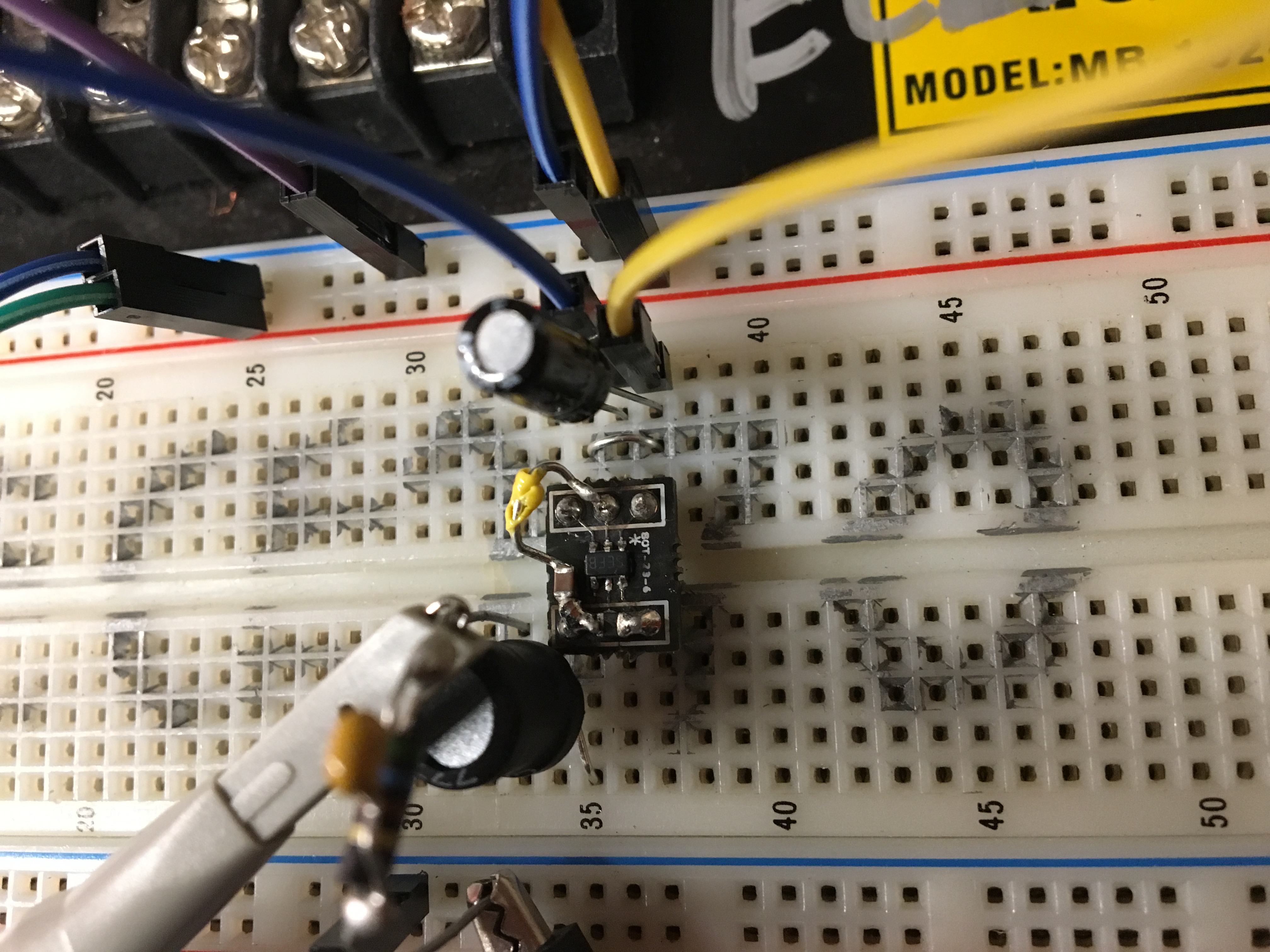
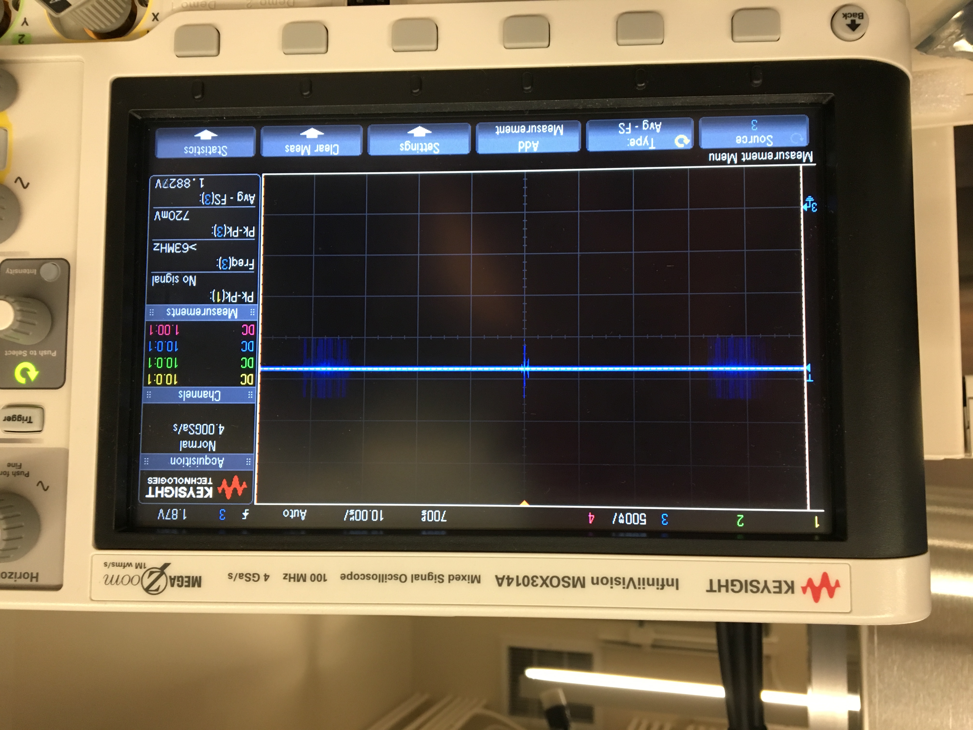
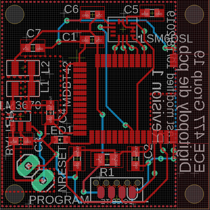
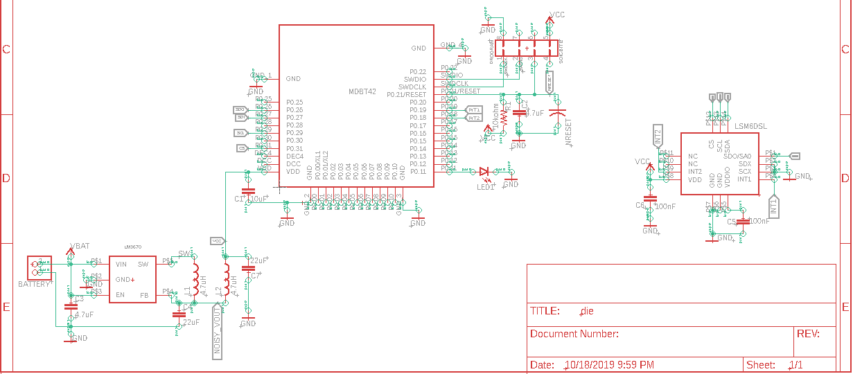
My main design contribution this week was doing more work on the PCB and doing some more testing on our chosen hardware to make sure they are functioning as expected. To start I hooked up our XY plotter to the motor controllers and tested increasing the frequency to better determine a speed we would want to use in our final design and to help determine possible thermal issues in our PCB design. I also build and tested the LM3670 buck converter we plan to use for the die and it gave the expected output. The output needs to have more filtering to further reduce the noise of the output voltage, so I plan to leave some blank pads on the PCB at the output in order to add a low-pass filter or leave blank as needed. Finally I did some more work on the PCB design and have been designing our new intended microcontroller for the die the nRF52832 which comes in a prebuilt module the MDBT42 which will help to make the PCB layout simpler.
Week 9
Due Date: 10-18-2019
Total hours: 50 hours
Description of design efforts: My main design effort has been finishing up our PCB's. I have ordered the die PCB but need to make adjustments to the main game board PCB before ordering it. I have also been giving some input on programming the nrf52832 and helping to get it interfacing with our IMU. I have also minorly assisted in the construction of our test enclosure by helping cut pieces. However, my main effort has been working on the PCB's. For next week my main effort will be finishing acquiring the parts needed and doing more practice soldering before our PCB's arrive. I will also be assisting in further developing our dice enclosures.
Week 10
Due Date: 10-25-19
Total hours: 12 hours
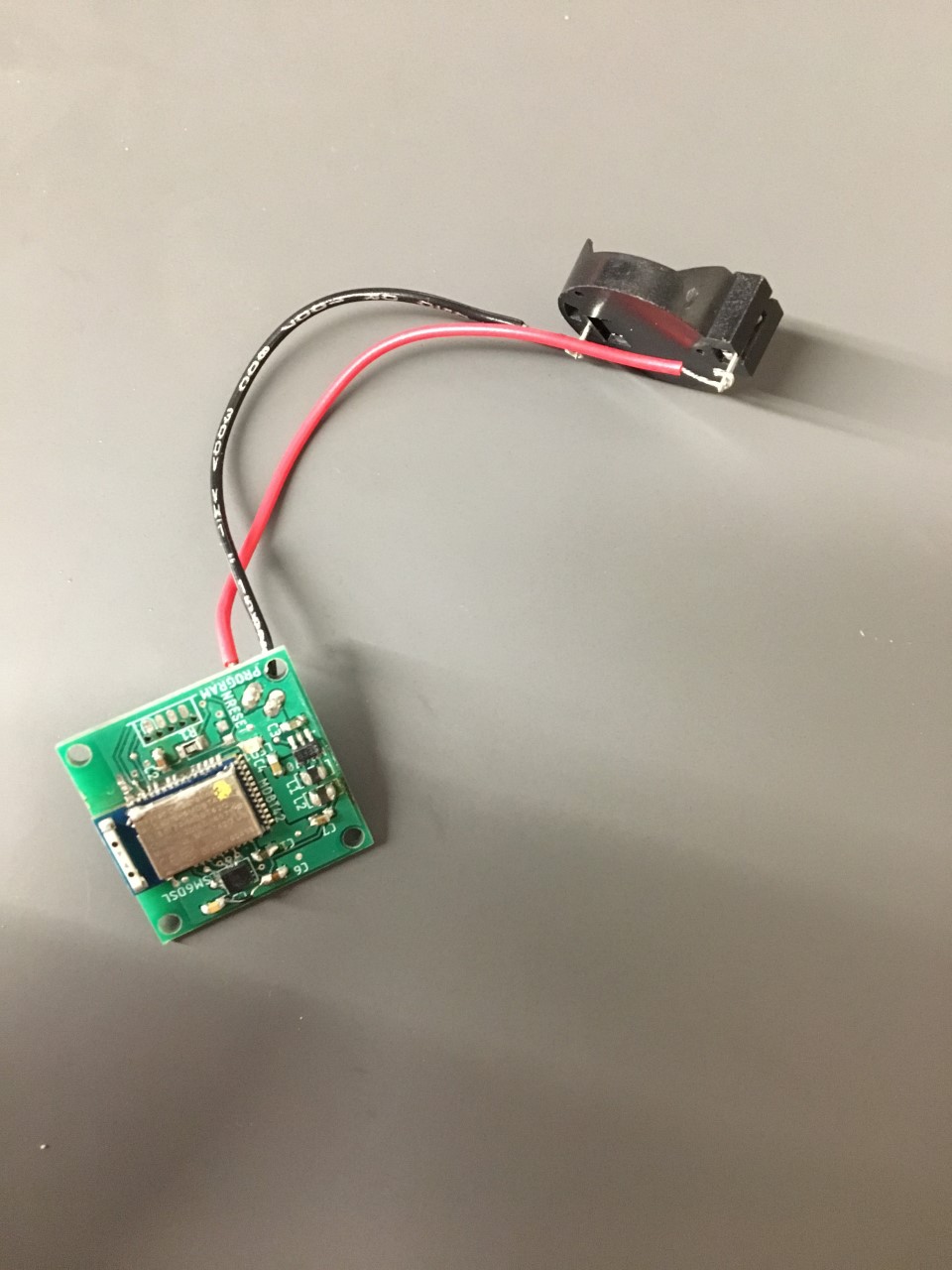
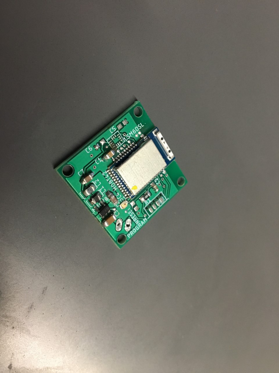
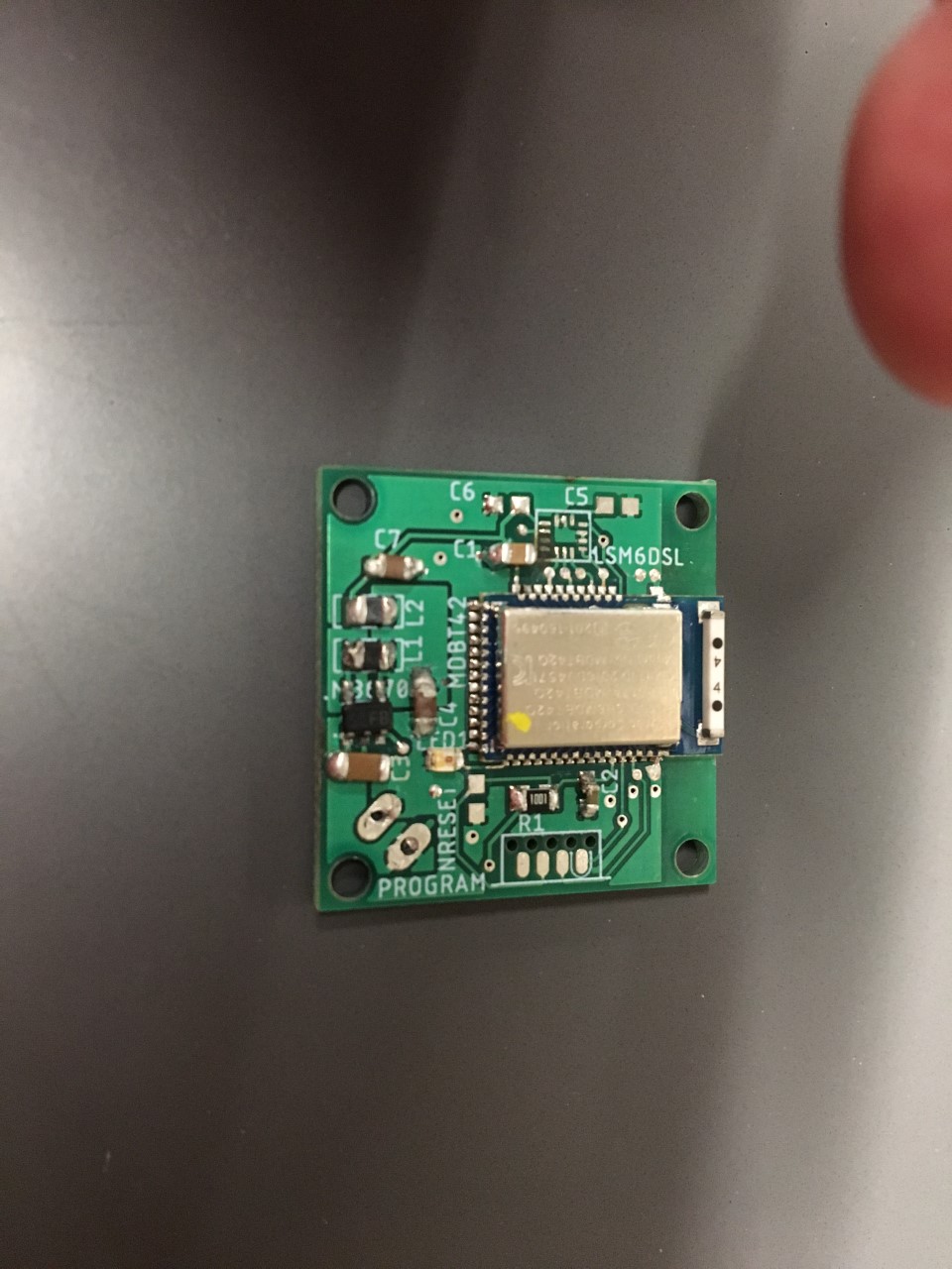
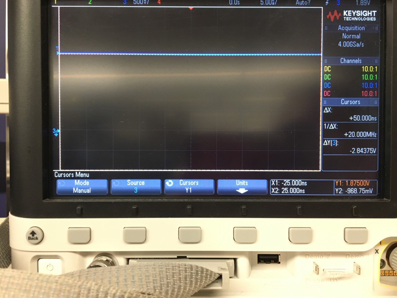
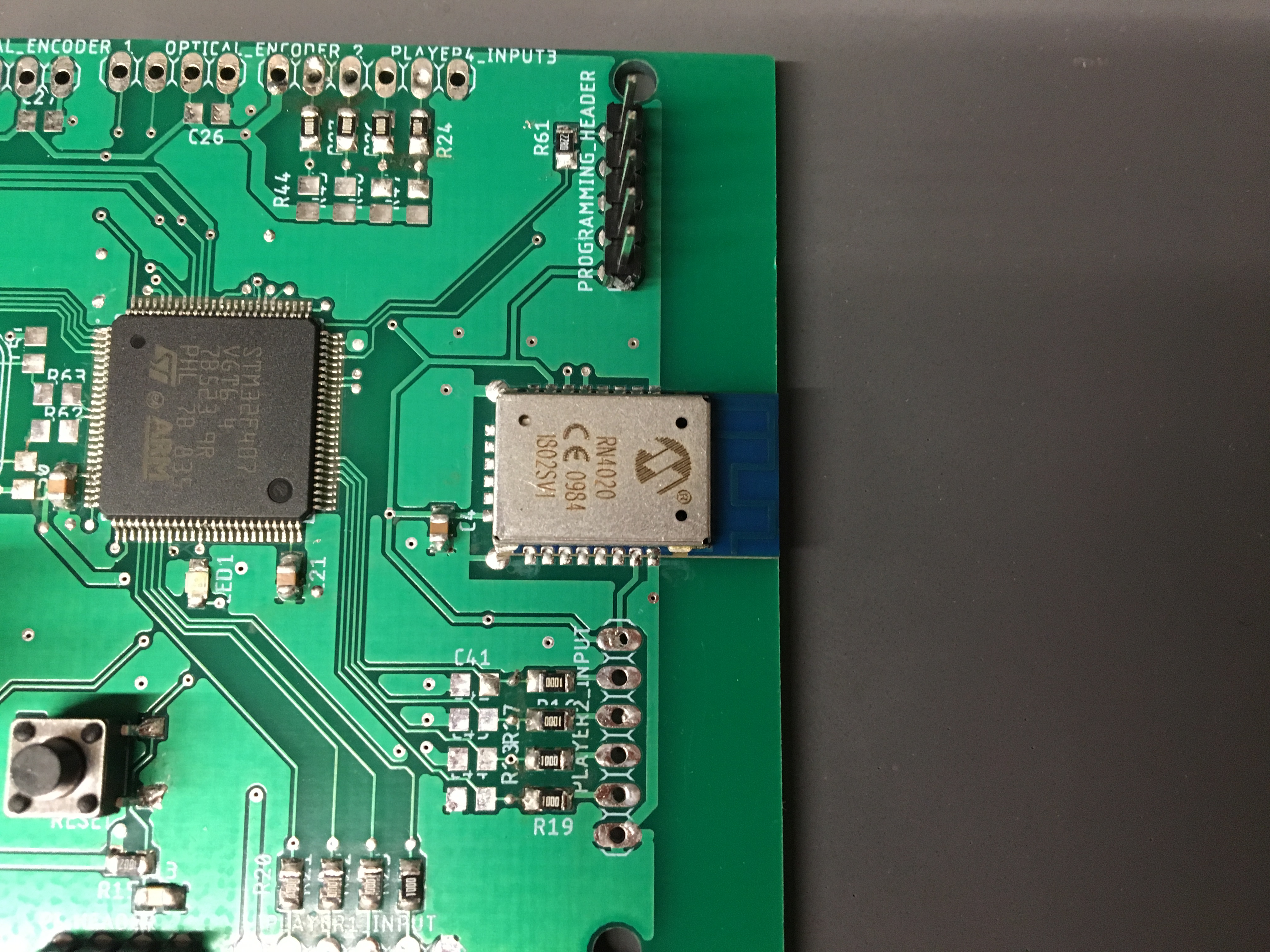
Description of design efforts: My main design effort this week was finishing up the PCB for our main board and getting it ordered. We also received our dice PCBs and I began verifying and populating one of them. So far I have soldered and tested the LM3670 which is being correctly filtered and outputting a constant 1.875V as expected. I have also soldered the MDBT42-Q, its decoupling capacitor and heartbeat LED. After looking at the board under a microscope all of the pins appear to be making good connections, and I have not been able to find any shorts with a DMM. My next step is to program it with an LED toggling program to test it. Once I verify that this is working I plan to solder on the IMU and then work on the second die. After finishing soldering the dice I will move onto verifying and soldering the main game board.
Week 11
Due Date: 11-1-2019
Total hours: 16 hours
Description of design efforts:
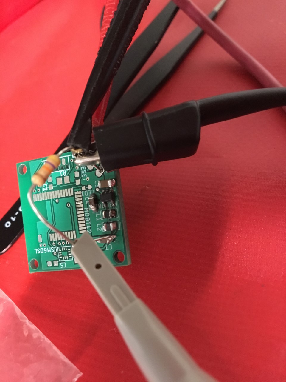
My main design effort was working on testing on finishing soldering the die pcb and running a blinking LED test. We had a number of issue using the IMU due to there being a short between 2 pins but once this was discovered and fixed it worked correctly. Once this was done I moved onto working on the main game board PCB. I got the power circuitry soldered on along with the STMF4 and programmed it with a blinking LED program. My next main design effort will be to finish soldering and testing the main game board PCB and to solder the second die PCB.
Week 12
Due Date: 11-8-19
Total hours: 12 hours
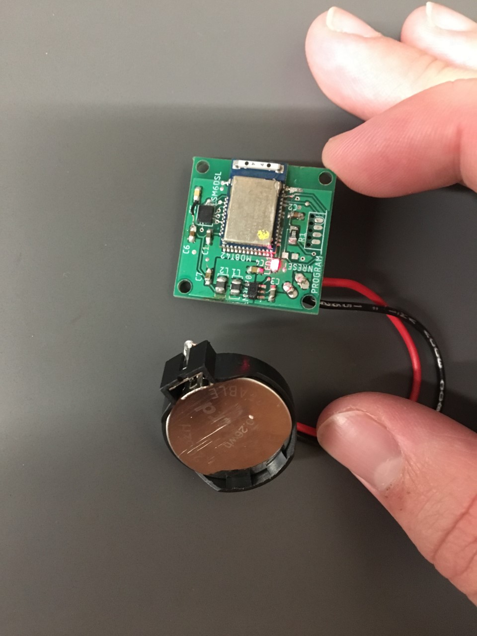
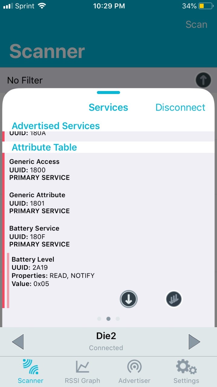
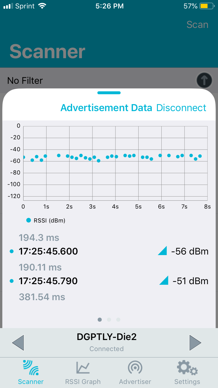
Description of design efforts: My main design effort for this week was soldering the second die. Everything is currently soldered on and the nRF52 is able to connect via bluetooth but the IMU is not working. It will likely need to be resoldered but more testing needs to be done first. I also soldered the RN4020 and the MCP73811T battery chargers on the main game board. The RN4020 was tested with the first die and it was able to receive the value of the die roll. The battery chargers have been tested and are working properly. My next main design effort will be working on fixing the IMU and to solder the motor driver circuits onto the main game board.
Week 13
Due Date: 11-15-19
Total hours: 12 hours
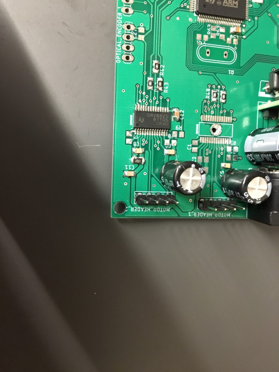
Description of design efforts: My main design effort for this week was finishing our second die. There was a short across one side of our IMU and I spent considerable time trying to fix it. It was eventually fixed and once this was done the second die worked completely and as expected. My other main design effort was soldering on our motor controllers (DRV8825). I realized there was a possible issue with the traces going to the sense resistors being too small. This is fixable by changing the voltage at this point by changing the resistor values at the voltage divider supplying it. I soldered all but a couple resistors and a capacitor for one of the DRV8825's and will be testing it once this is done. My main effort for next week will be finishing soldering the main game board.