
Niraj Menon
Progress Report
Week 1
Due Date: 23rd August 2019
Total hours: 5 hours
Description of design efforts:
Initial design phase during which I set up a skeleton framework for the website, helped write up the final project proposal and starting doing basic research on required parts for our project.
Week 2
Due Date: 30th August 2019
Total hours: 8 hours
Description of design efforts:
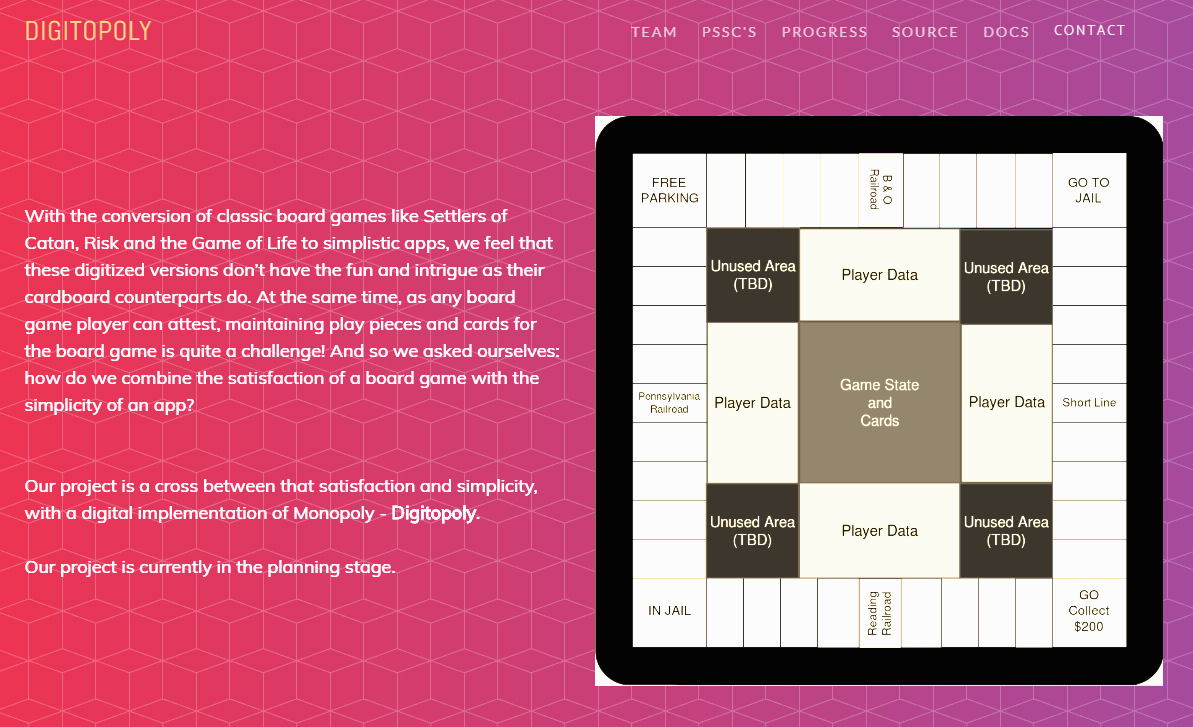
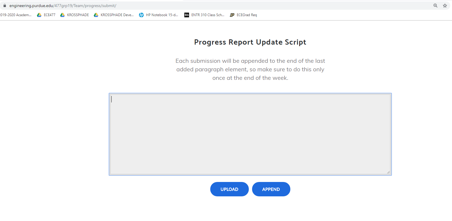
I created a submission portal that made it very easy for team members to upload their progress reports instead of directly editing the HTML. Team members will login to the portal (screenshot attached below), enter text and upload relevant pictures, and click Submit, invoking a CGI script that will format the text and pictures with HTML tags and append it to the end of the page. Source code may be viewed here.
I started work on a library that will simplify controlling the XY plotter via the microcontroller. By abstracting the complicated procedures needed to move the centerpiece to a specific position, I plan to create simple functions that the game logic can call in order to ease development down the road.
I also wrote out the Functional Description, Theory of Operation, Computational/Electronic and Mechanical Constraint sections of the Functional Specification document.
Week 3
Due Date: 6th September 2019
Total hours: 12 hours
Description of design efforts:
I created a TODO list for our software development on our whiteboard that would help keep things organized as we moved along.
I modified the progress report update script to accept videos in addition to images.
Alex and I managed to interface with the STM32F4 we wanted to use in the project and got our first blinky program working. The aforementioned video depicts the blinking on the scope (we didn't have LEDs at the time) which was hooked up to PC0 on the microcontroller, which was set to blink roughly every second.
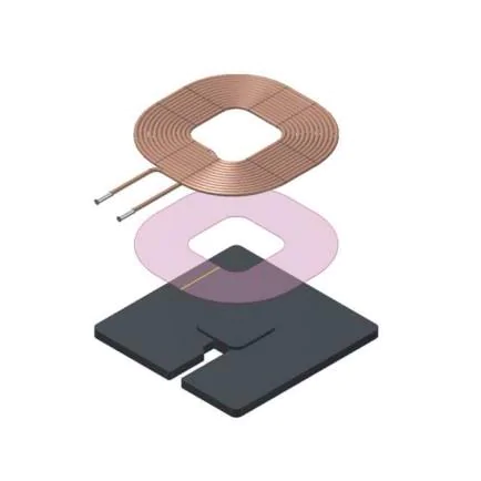
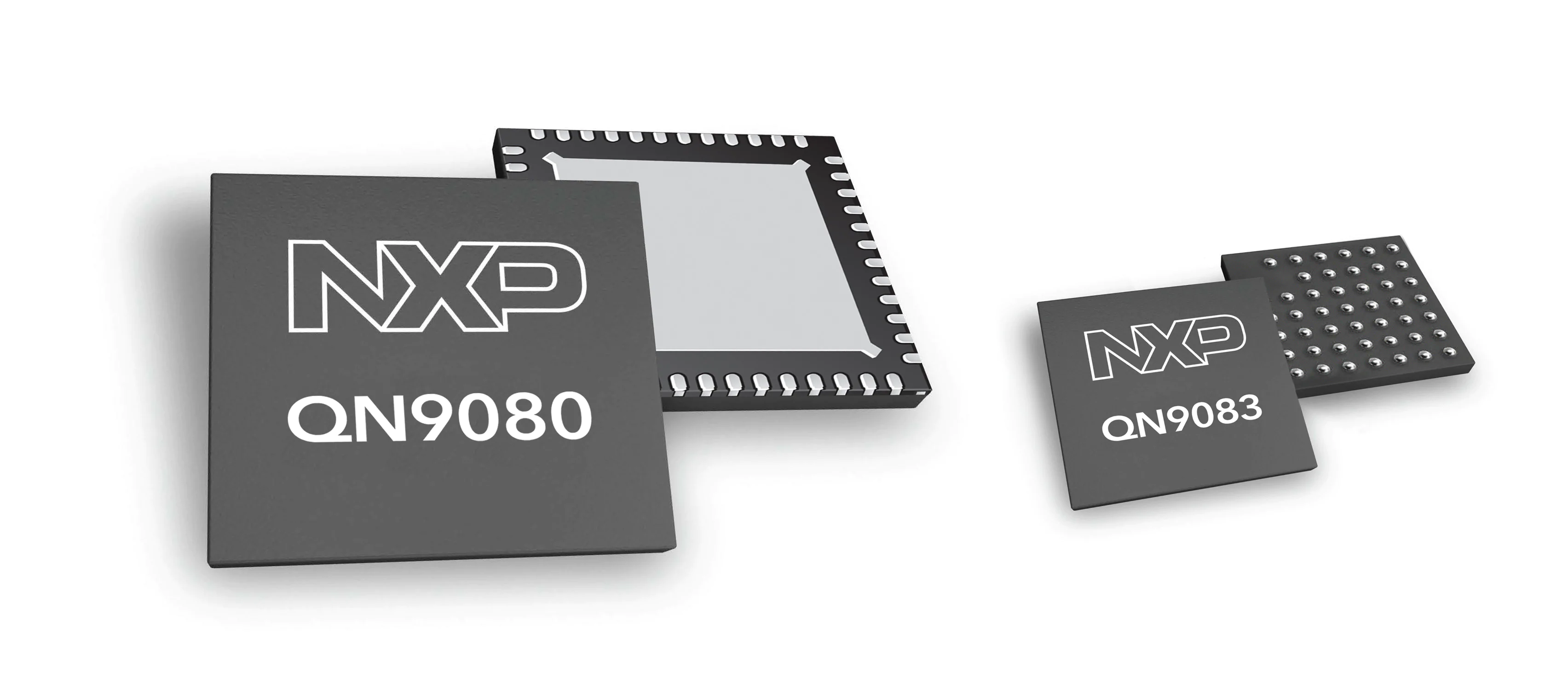
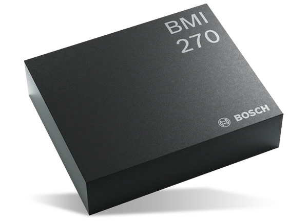
I was performing extensive component research this week on what we could use for the wireless die. I was intrigued by ULP (ultra-low-power) components, which I thought were critical to reducing power consumption on the die, which would have a very small battery and hence would require power consumption to be as close to zero as possible. Some of the parts I was considering are linked here, here and here, and pictures of the components (a wireless coil, a ULP IMU from Bosch, and an NXP ULP microcontroller with Bluetooth) are also attached.
I helped Karthick with the Software Overview document and expanded on the reasoning behind the component choices in the Component Analysis document.
Week 4
Due Date: September 13th 2019
Total hours: 10 hours
Description of design efforts:
I started working on the Raspberry Pi side of things. The RPi will be used to display great graphics that we thought were crucial to the game. After setting up Raspbian on it, I did the following after performing some research:
- Removed all unnecessary packages to reduce boot times on power-up.
- Turned off Wi-Fi and Bluetooth since the Pi will be responsible for any game logic/communication.
- Set up a 'kiosk mode' by hiding all the desktop icons, the task bar, and making the background pure white.
To render the graphics accordingly based on communications with the main microcontroller via UART, I decided to use node.js and the Electron framework to create an app that starts up after the Pi fully boots up. This also made it easier for Karthick to use his extensive knowledge of the HTML5 Canvas element to create great looking graphics for the board and the logic needed to manipulate them. Attached is a video showing the Pi's current boot up process, then loading the game.
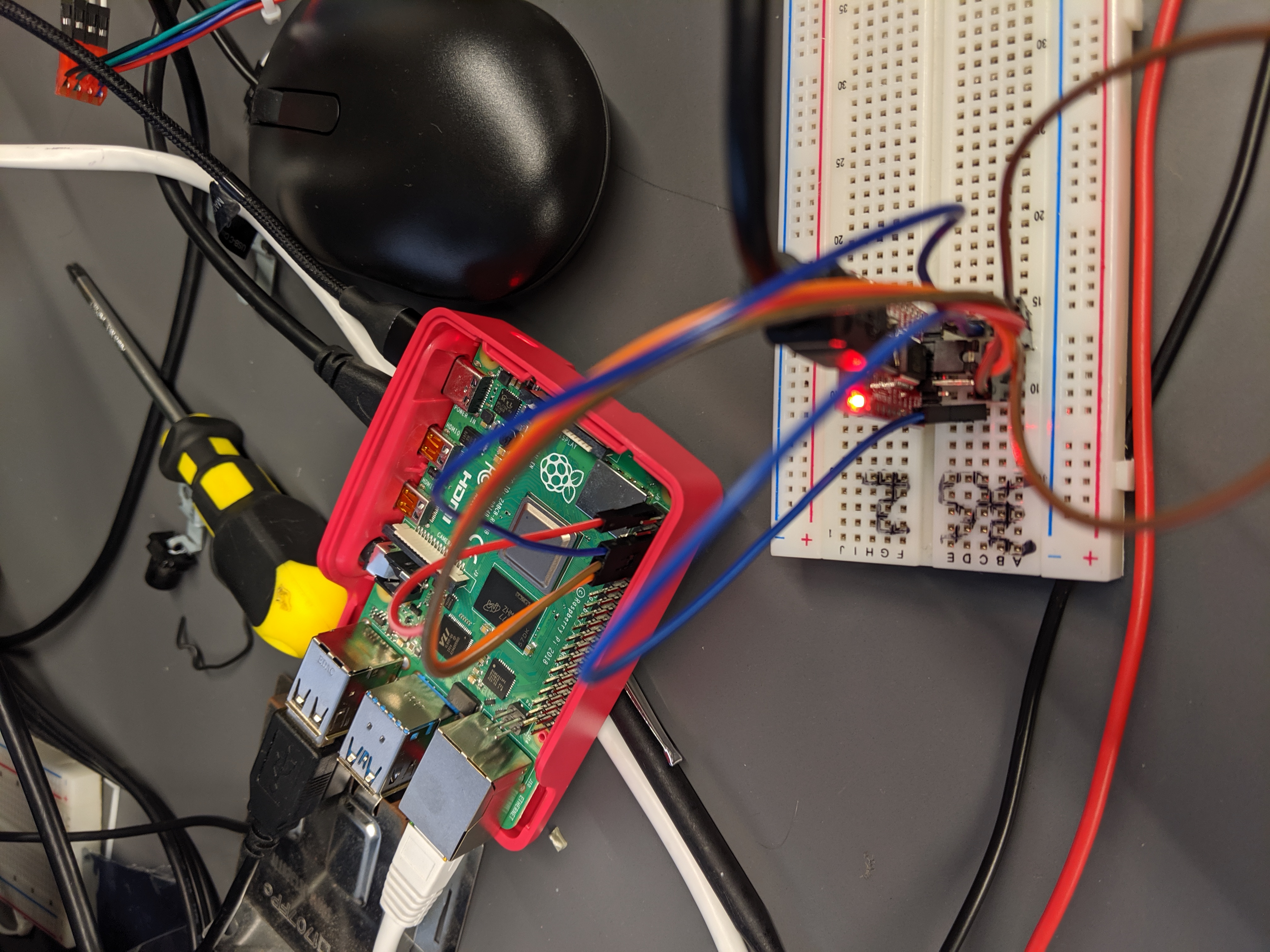
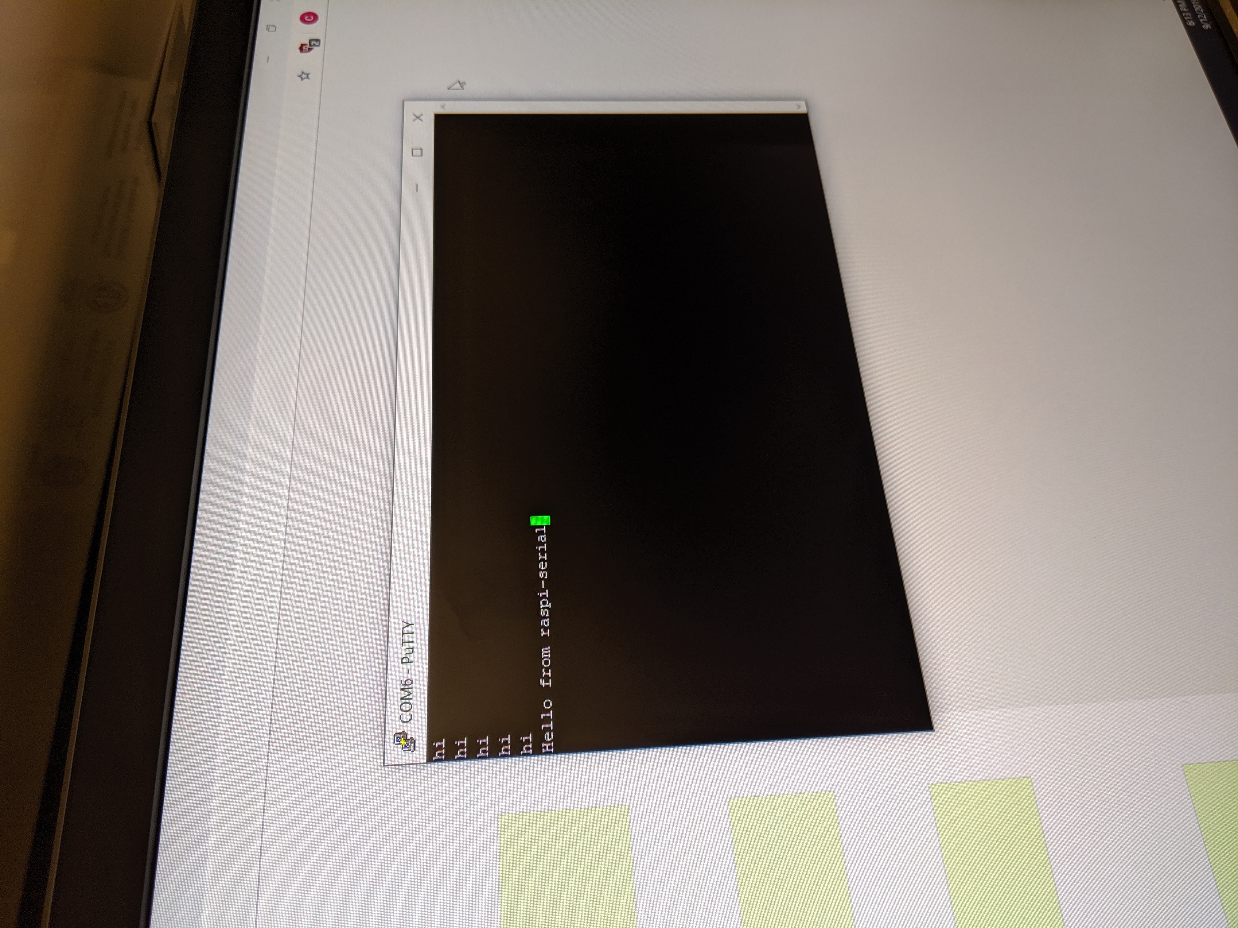
I also found a node.js library called raspi-serial that allowed for very easy setup of the onboard serial port for communicating using UART. After some extensive trial-and-error, I managed to enable the serial port and communicate with the lab computer over PuTTY and a USB-to-Serial converter (FTDI232 chip). A picture of the setup is attached, along with some "Hello world" attempts!
Karthick and I are still working on UART on the STM32, which is proving a little bit more difficult to manipulate than the Pi's UART.
Week 5
Due Date: 20th September 2019
Total hours: 8 hours
Description of design efforts:
During this week, we focused a bit more on creating wrapper functions on the STM32 to be able to send data more easily to the Pi. We decided to go with the JSON exchange format to send data from the STM32 to the Pi because in that case the receiving node.js process on the Pi could simply use the in-built JSON library to parse and manipulate JSON objects coming in from the STM32, and the only extra work we would have to do would be to write a rudimentary JSON generator on the STM32 in order to send structure data, which is already in a format very similar to JSON.
Karthick and I decided to play around with inputs to the STM32 and the Pi - in particular, a power button and a scroll wheel + button to be handled by the STM32. We started with the scroll wheel by dismantling an old mouse, finding the scroll wheel mechanism (the physical wheel attached to a device similar to a potentiometer) and analyzing the waveforms that came out of two pins if the third pin was hooked up to 5V power. We figured out a pattern with the two waves upon turning the wheel, as indicated in the video attached. When turning in a specific direction, we found that one of the waves would go high before the other. Further turning (presumably to the middle of the turn) caused both waves to go high. The first wave would go back down followed by the second when we turned the wheel to the end of the turn.
I also worked on the Commercial Product Packaging section of the Mechanical Overview section.
Week 6
Due Date: 27th September 2019
Total hours: 8 hours
Description of design efforts:
After getting the UART to work correctly between the Pi and the STM, I decided to continue working on the data protocol for the link. We had decided to go with the JSON data format simply because it was easier to parse on the node.js side, allowing us to focus on coding up game logic more easily on the STM. I managed to get the STM to communicate scrolling actions to the Pi.
The idea we were trying to implement was that when the scrolling wheel turned in either direction, it's corresponding pin on the STM would trigger an interrupt, which would detect the direction of the scrolling, and then transmit a JSON object like {"action": "scroll", "direction": "up"} which the Pi would run through a complex case statement, first based on the action, and then changing the basis depending on what the action element was. In the case of scrolling, the "action": "scroll" indication would then direct the Pi to run either a JavaScript scrollUp or scrollDown function depending on the next indication, which was the direction, be it "up" or "down".
Unfortunately the mouse scroll wheel that we were using had far too much noise which when plugged into the STM kept triggering the interrupt when we simply touched the wheel. We decided to go for a joystick, but then we couldn't figure out how to start the ADC on the STM, which we were stuck on for days. We decided to go with the digital option of a rotary encoder - it functioned like a scroll wheel with no noise, and wasn't too hard to turn if you put a knob on it. The video attached shows the scrolling event in action, which we hardcoded into the STM for 'show me a thing' this week.
Week 7
Due Date: October 4th 2019
Total hours: 10 hours
Description of design efforts:
This week, we went into a bit of a backslide. The UART and external interrupts on our STM32 started going haywire, and we weren't able to figure it out. To make matters worse, the node.js package we were using to control the serial port seemed to have auto-updated, and now no longer works. I have been trying to debug and fix things but to no avail - it almost seems as though the STM32 is broken and the node.js serial port package has broken something internally in the recent update that we will not be able to pinpoint.
At some point I decided to back up the game display code on the Pi and just go nuclear on the SD card and reinstall the OS. Upon doing so, we reinstalled node.js but we found that the issue was never with the OS - it was with the
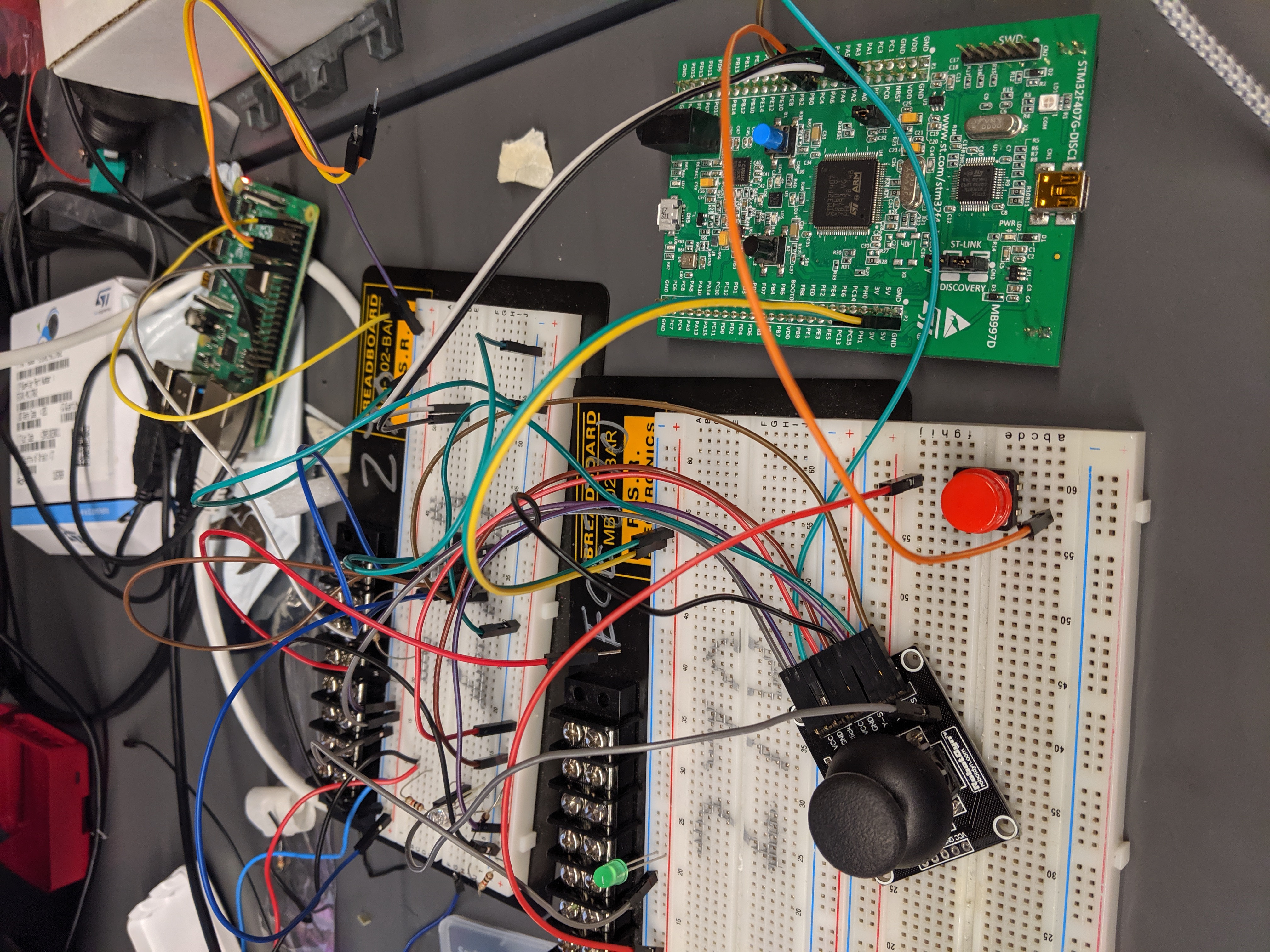
I was also phasing in and out of figuring out what had happened to UART on the STM eval board. The UART works very rarely, spitting out action commands like I had described in my previous progress report, but upon attempting it in debug mode, completely stops working. I am currently leaning on the idea that the STM32 may indeed be fried, and we may need another one. Attached is the setup I'm working with.
Code-wise we are still making progress on implementing more high-level functions such as buying and selling properties. Karthick had finished the struct development for all the possible objects (Players, Properties, Chance/CC cards, etc.) and we only just started working on functions for manipulating those structs.
I finished the Software Formalization document this week, with the other team members proofreading it.
Week 9
Due Date: October 11 2019
Total hours: 13 hours
Description of design efforts:
We managed to move forward on development with the main micro and the Pi, after we kept getting stuck on the external interrupts from the user buttons. We now have a proper scroll up/down button set, which we can later reprogram as optical encoder input lines easily once the PCB arrives. It took a long time, but we finally started moving forward.
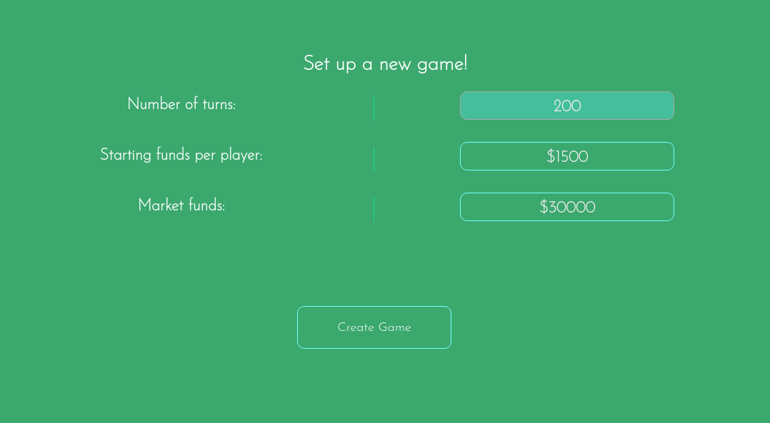
We also started fleshing out the main menu into the New Game, Load Game, High Scores and Credits. New Game is finished cosmetics-wise, and now we're working on the STM side of things.
We had our midterm design review and due to a fatal save error with the Eagle design software, our routed PCB data got lost. As a result we were not able to present it in time for the review, which we could've been better prepared for.
Week 10
Due Date: 10/25/2019
Total hours: 8 hours
Description of design efforts:
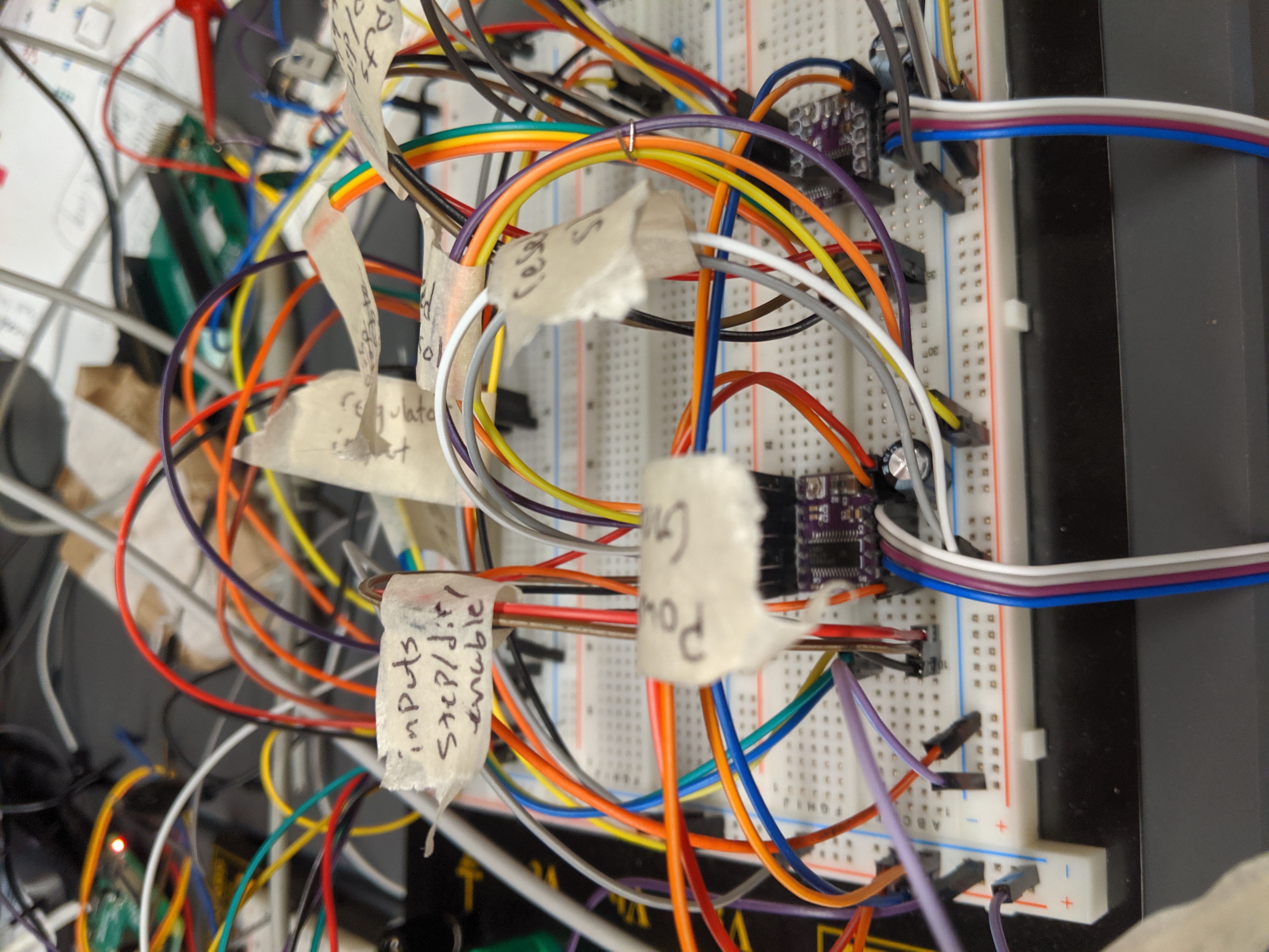
This week, I was working on writing firmware for actually moving the motors to specific positions, by extending the work I did on actually writing code to move the motors in different directions by toggling direction, step and enable lines to the motors from the microcontroller. The dir/step/enable lines are meant to go into our circuit for driving both the motors (with two pairs of these three lines for each of these motors) and will go to six pins on the micro. I am still in the design phase, since there were things to be considered like the fact that only one motor has to move at one time because the piece is only moving along the sides.
In addition, I was adding more elements to the new game menu. It is a little bit tricky to figure out how to set the elements because we had covered up the screen in order to make it square with a smaller size. What I had done on Wednesday has been attached, since I submitted this report a bit late and didn't have access to the Pi at the moment. I had made some more progress after that.
Week 11
Due Date: November 1st, 2019
Total hours: 7 hours
Description of design efforts:
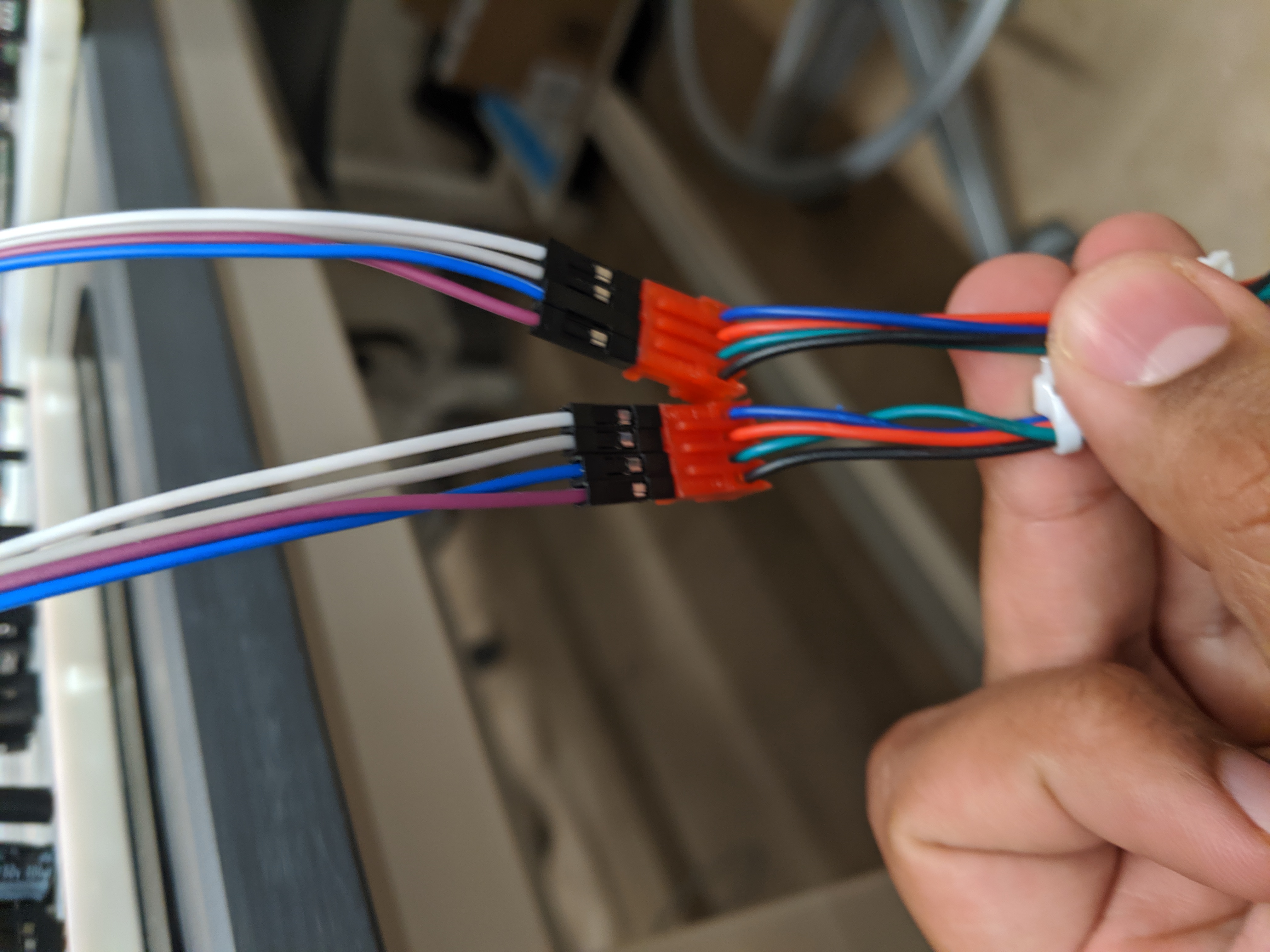
Unfortunately, we regressed again this week when it turned out that our motors had (seemingly) stopped working. I had to end up rewiring our circuits again, and fixing the labels because it turned out that some of them had been connected to the wrong pins on the motor controller (but our motors were still working is a mystery.). The rewiring process is attached.
I managed to add some more control on how the motors were moving, implementing functions to quickly toggle direction and enable signals to the controllers, and set up timers to act as the step signal to the motors. A good test of this was by instantiating a loop in main that would move the motors from 'home' to one end of the board on the y axis, then move it to the other end on the x axis, and then all the way back. I want to figure out how we can capture how many times we have to toggle step to accurately move the electromagnet to a specific position, to be able to move pieces correctly.
Week 12
Due Date: November 9th 2019
Total hours: 5 hours
Description of design efforts:
Continued to write code for the plotter, still waiting on the optical encoder mount that we could use to detect where the motor has moved to.
Week 13
Due Date: November 15th 2019
Total hours: 10 hours
Description of design efforts:
We realized that the way we had set up the display on the Pi was extremely hard to manipulate. Karthick had designed it well using the Canvas element, but the ability of interacting with it using pure JS was harder than we expected, so I decided to redesign the board using DOM (using regular HTML with styled divs and overlays).
I redesigned the basics of the screen in the DOM, and got a basic demo working that has been attached.
Last week, I had been working on the plotter code to do more high level stuff like position-to-position movement, so functions like move from (x1,y1) to (x2,y2). I didn't get too far because we're still analyzing the signals from the optical encoders on the rotating motors so we can figure out where exactly the central electromagnet is, and I'm holding off until we get the encoders to work the way we want them to. On Friday, we got a stable signal while rotating the motors for like three seconds before it disappeared. We're considering options like maybe cleaning up the signal with caps if needed.
I also wrote up the User Manual document due this week.