Karthick Shankar
Progress Report
Week 1
Due Date: 08/23/2019
Total Hours: 5 hours
Description of Design Efforts:
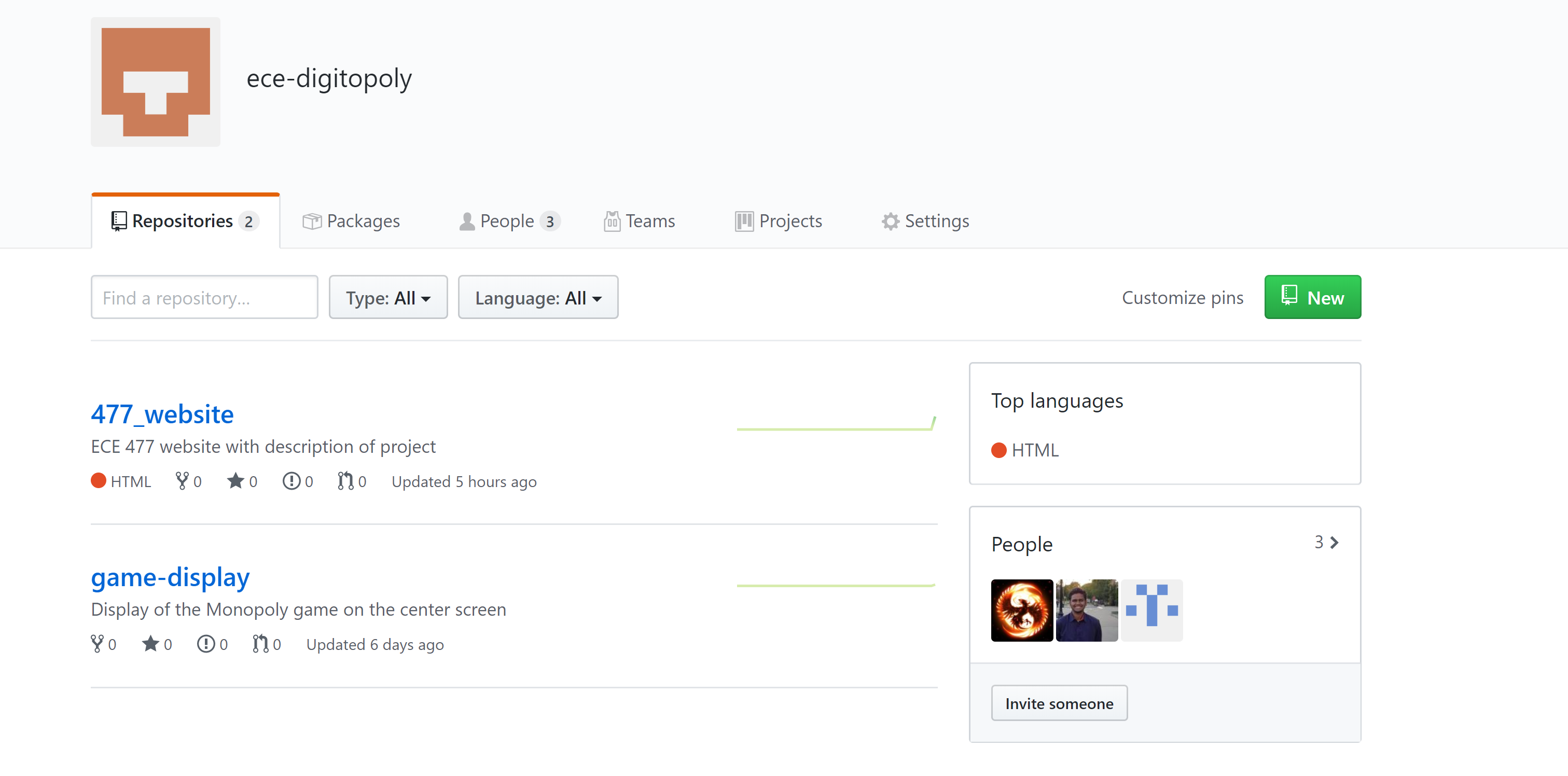
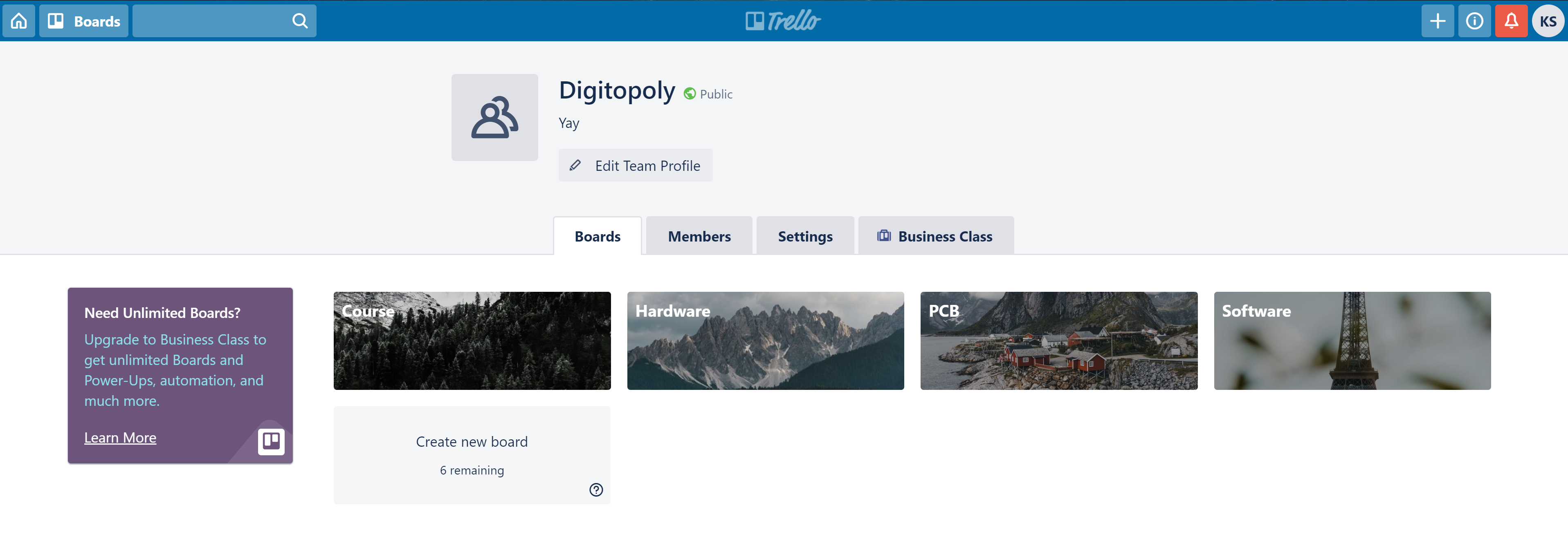
Since this was the first week, I spent some time setting up some tools for project management. This would ensure a smooth workflow for the team and limit confusion. I set up a github organization where all the repositories for our code will lie. This is better than having it on personal accounts where tracking becomes a hassle. I also set up Kanban boards on the popular website trello for each section of the project to ensure that we are working towards specific tasks and are able to scope the features out early on.
Week 2
Due Date: 08/30/2019
Total Hours: 7
Description of Design Efforts:
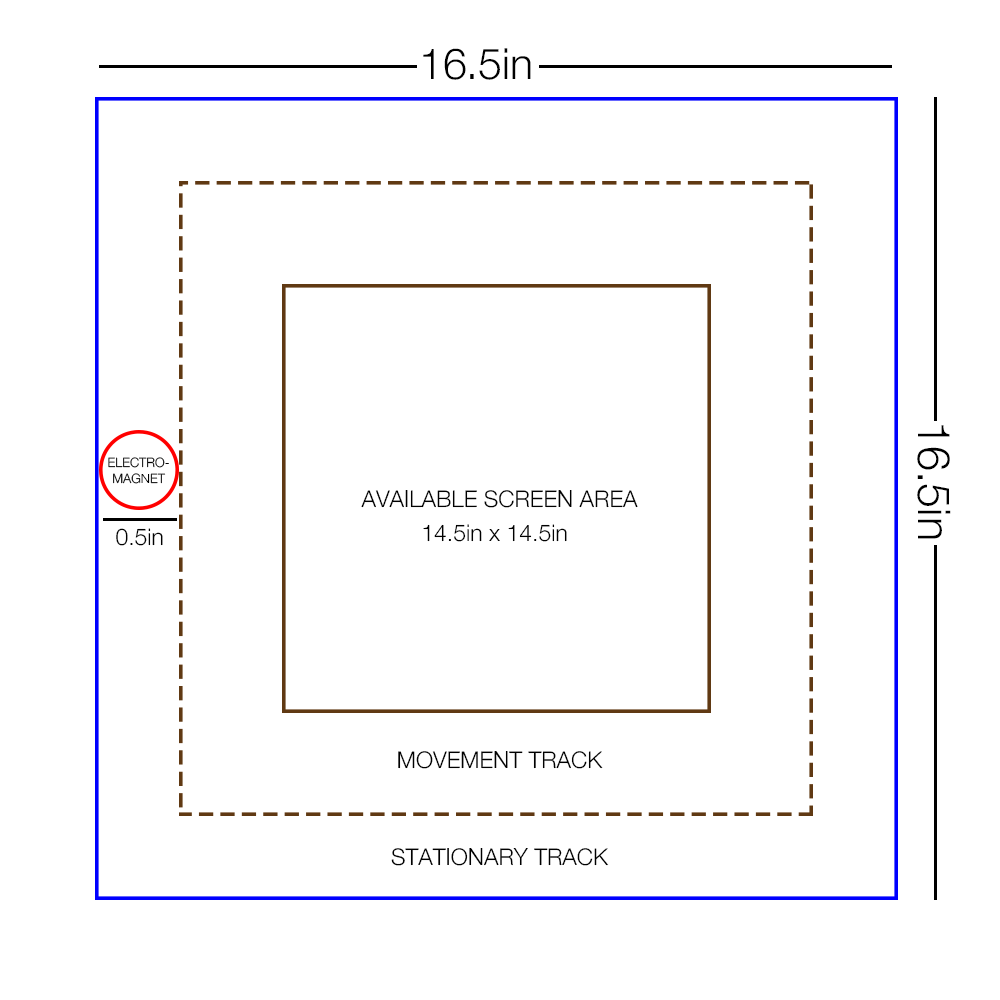
This week, I started off by assisting Alex when wiring up the XY plotter motors to the H bridge (DRV8825). I then moved on to look at possible options for monitors and scoping out the sizes of our subsystem so far. The movement track mentioned in the image is the track that the pieces will move on while the stationary track is the track where the pieces will be placed onto. As the image below shows, there’s a very specific size that our monitor must be (14.5in x 14.5in maximum) to maximize viewing pleasure and still have space for the electromagnet. The existing electromagnet that came with the XY plotter had a diameter of 1in which is too big for our project unless we decide to sacrifice on screen real estate. I found an electromagnet with a 0.5in diameter but it has half the amount of force, so we will have to evaluate those requirements soon. The monitors that work best for this are those with a 4:3 aspect ratio, commonly found these days on CCTV monitors. I picked out a couple different monitors on Amazon (monitor 1 and monitor 2)for us to consider if the one we already had was too big.
Also, I started preliminary design work on what the screen would look like and started scoping out exact placements and fonts.
Week 3
Due Date: 09/26/2019
Total hours: 7 hours
Description of Design Efforts:
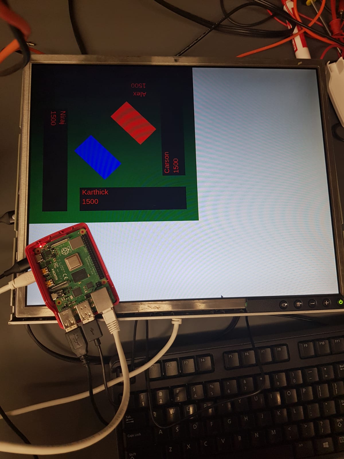
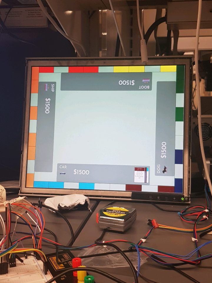
This week, I was mainly working on the Software Overview document and was writing preliminary code to display the game board. I used JavaScript to make classes for the player and community chest and chance cards and displayed them on a canvas object. The code can be found on the github repo. I hooked up the RaspberryPi to our display and ran the code to get an idea of the sizing of the digital board as shown in the image.
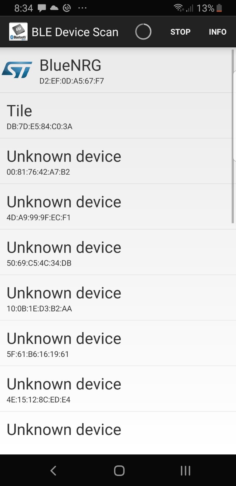
I also started testing our Bluetooth breakout board (the STEVAL-IDB007V1M) and recognized the device on my phone as shown in the screenshot.
Week 4
Due Date: 9/13/2019
Total hours: 10 hours
Description of Design Efforts:
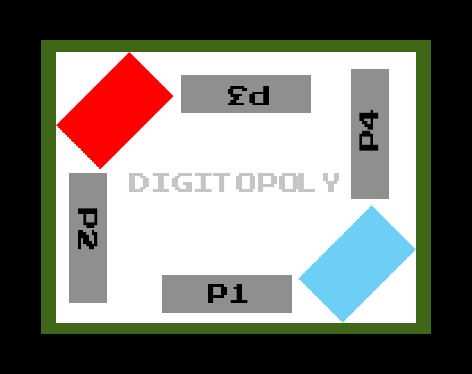
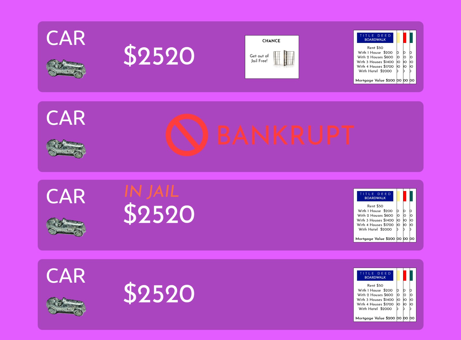
This week, I primarily spent the most time on flushing out the software shown in the previous reports. As shown in the image below, the game board has taken a basic shape with 4 player bars, property cards if a player has bought them, icons and names for each player and the running money count for each player. Before I implemented them on the Raspberry Pi application, I wireframed some designs for the player bar that are also shown below. I hope to complete the other states of being in jail and bankruptcy in the next week.
I also worked with Niraj to test the UART capabilities of the Pi and the STM32F4. I worked on the STM32F4 with the HAL drivers to try and get UART to work, but I ran into a couple linker errors that I also hope to fix soon. On the Raspberry Pi side, Niraj and I used an npm package to get UART and read the values correctly on the oscilloscope.
Week 5
Due Date: 09/20/2019
Total Hours: 8 hours
Description of Design Efforts:
This week, I started off by ripping apart an old mouse to understand the logistics of the scroll wheel along with Niraj. The potentiometer was soldered to the board and I removed the solder to get just the potentiometer. As shown by the video in Niraj’s progress report, we wired up a circuit to see how the wheel works on the oscilloscope. I then moved on writing some code for the microcontroller to read the output of the scroll wheel with GPIO, but since the potentiometer was just connected with jumper cables, the connections weren’t strong enough to get a smooth signal. The next step for that is to potentially solder it onto a protoboard to make it easier.
I also worked on writing the code to send JSON information from the STM32F4 to the Raspberry Pi. I wrote a few functions that sent over dummy action data over to test the communication aspect.
.jpeg)
.jpeg)
Week 6
Due Date: 9/27/19
Total hours: 6 hours
Description of Design Efforts:
This week, I had two primary tasks. The first was to start writing code for gameplay on the STM32F4. We are using C++ so I started defining classes for each aspect of the game. Currently, I have the state machine set up for landing on a property and the actions that a user has to take after that. As defined in the software overview, there is an action class that takes an action based on the current game state and player position.
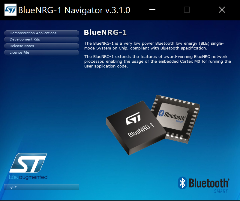
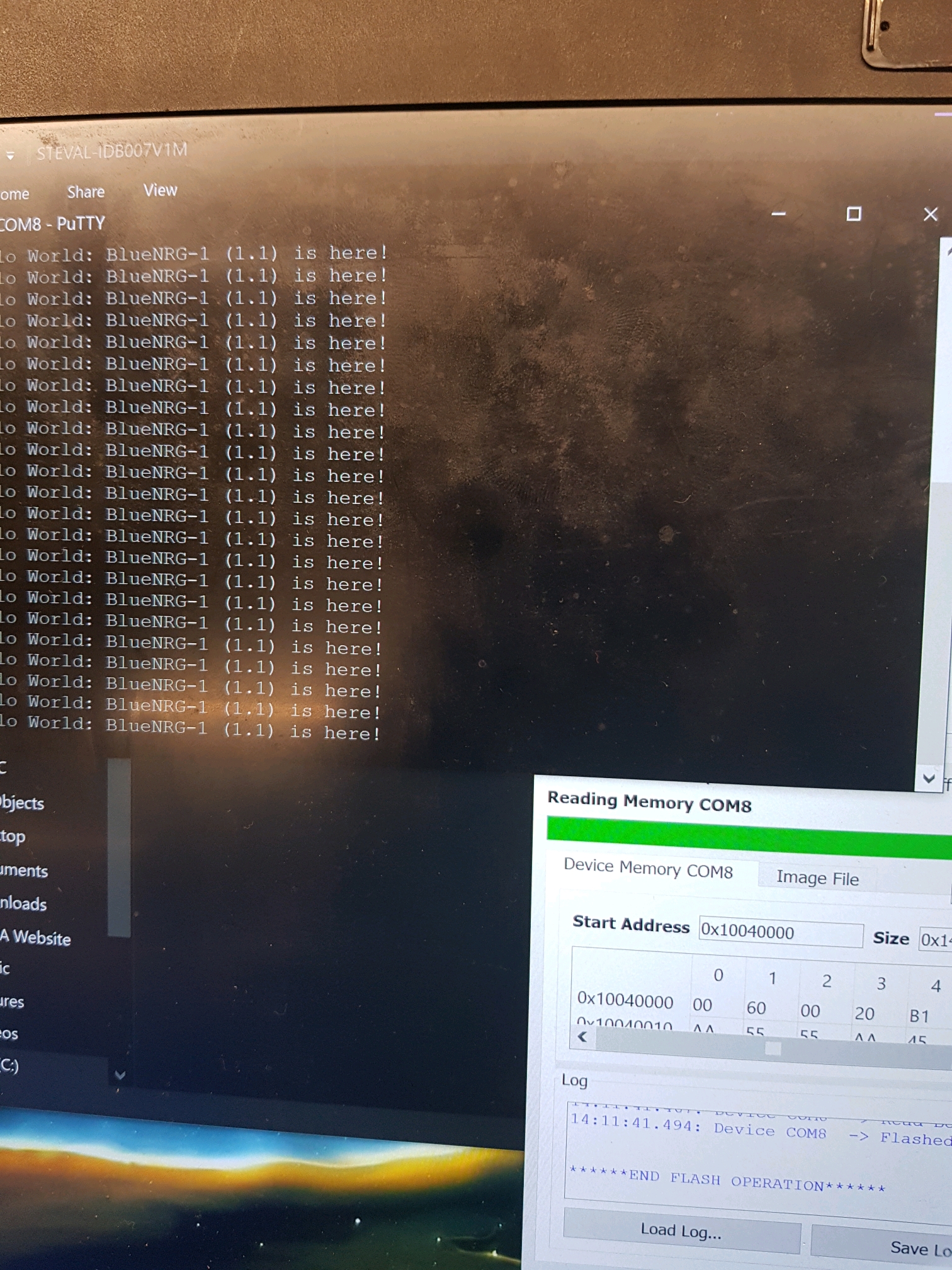
The next goal was to interface with the SPBTLE-1S bluetooth module on the STEVAL-IDB007V1M. The documentation was primarily defined for another module (the BlueNRG-1, the navigator of which is shown below), so information was sparse. I downloaded different toolchains namely Keil MicroVision and ST's Atollic to try and interface with it. Upon fixing numerous bugs, I was able to flash a piece of code onto the module to send a basic hello world message through UART as shown below in the image.
I also got started on transmitting orientation information from the IMU to the STEVAL board, so that will be my primary task for next week.
Week 7
Due Date: 10/04/2019
Total Hours: 5 hours
Description of Design Efforts:
This week I continued work on the Bluetooth modules. I was having issues with the SPBTLE-1S that only flashed and ran precompiled example binaries. The ones that I generated didn't run at all. So, to test out the code we got a breakout board for the BlueNRG-2. I was able to flash custom code on that correctly and have it broadcast messages on the general Bluetooth channel. Further, I wired up the RN-4020 Bluetooth module, which is a simpler module we plan to use on the main microcontroller. I was able to use UART to transmit basic commands to setup the interface. Then, as shown in the video, I was able to get the BlueNRG-2 and the RN-4020 to connect and go through the pairing process to be bonded. I didn't get to transmit custom data between them yet, which will come next week.
We are also considering another Bluetooth board since the BlueNRG-2 needs a custom antenna that requires more effort on the PCB side.
Week 8
Due Date: 10/11/2019
Total hours: 12 hours
Description of Design Efforts:
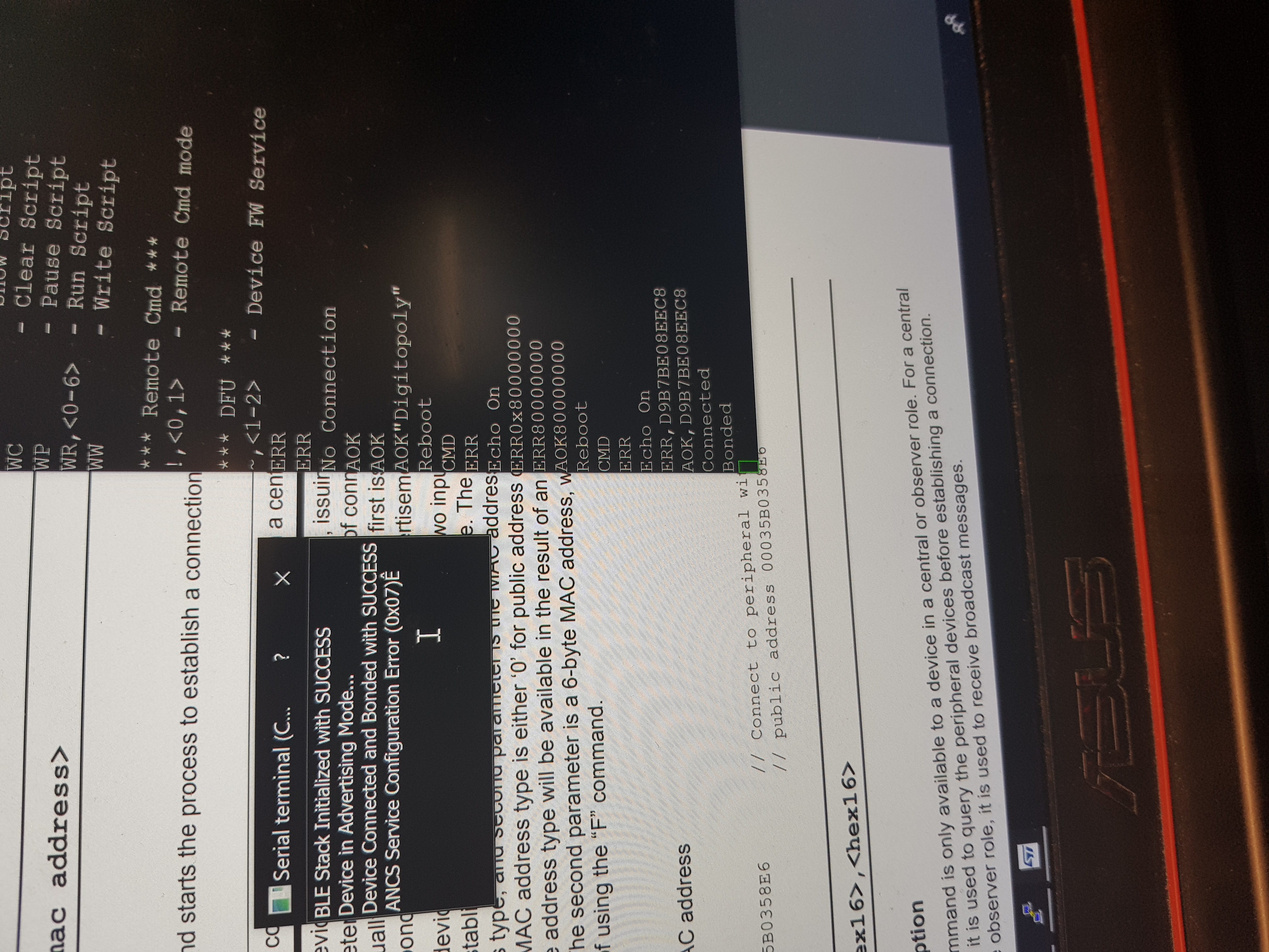
This week was primarily dedicated to design review prep. I wanted to get all the components tested and verified before the design review and since we switched our bluetooth module on the dice to the Nordic nRF52832, I started prototyping with that. I was able to use the SEGGER toolchain and was able to get it to advertise in peripheral mode. I then found this signal and connected and bonded this to the RN4020 which is on the main board. After that, I was able to send data from the nRF52832 to the RN4020. The data so far is random data in the pre-defined Heart Rate Sensor profile, Battery Information profile and the Device Information profile (as shown by the circle in the picture)!
The final component to test was the LSM6DSL IMU. I tried many different pieces of code with with different registers but I wasn't able to read any significant data with SPI. I was able to read some sections of the IMU like the gyroscope sensitivity, but I wasn't able to get actual orientation information. Once that is completed this week, all component testing should be complete!
Week 10
Due Date: 10/25/2019
Total Hours: 12 hours
Description of Design Efforts:
This week, I continued work on the dice subsystem and completed almost 90% of the process! I was able to get the correct gyroscope data from the IMU and I found a library on STMs website for the LSM6DSL to be able to convert that into readable data. After that, it was just some quick comparisons and I was able to get the actual die roll (i.e. 2 or 6 or 5 etc.) to print to the screen. The next step was to transmit this through bluetooth. The previous week, I managed to get bluetooth communication working between the nRF52832 and the RN4020 to send random data through the Heart Rate Sensor characteristic.
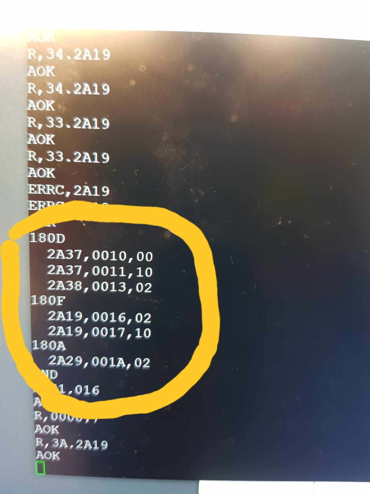
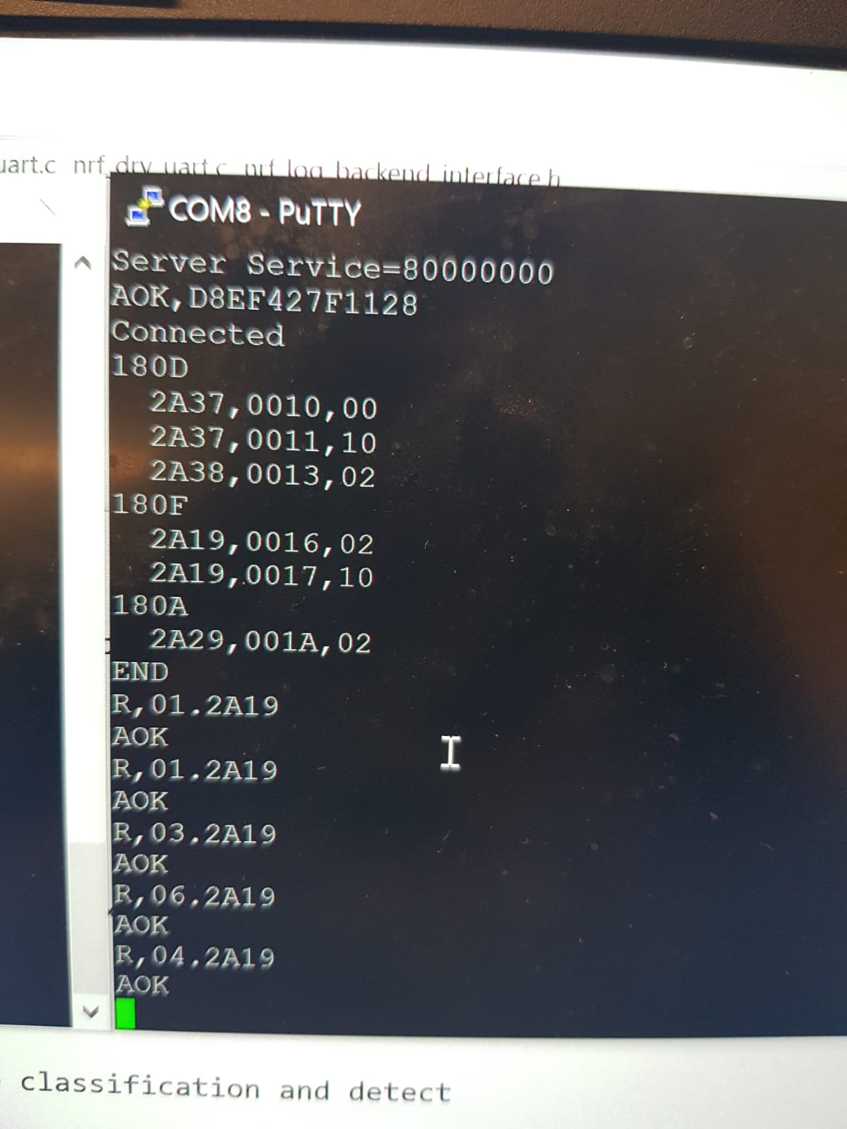
I adapted the code from that to use the Battery Information Characteristic instead since that uses lesser fields and thus transfers lesser data. I was then able to send the die roll data over to the RN4020! The picture attached has many lines that are of the form "R,0X,2A19" where X is a number. Anything except 0X is fragment of the echo command which I'm using so that I can see what I'm typing. However, X represents the actual die roll and that is successfully seen on the RN4020! Carson managed to finish soldering the nRF52832 onto the die PCB, so I will be able to test on the actual PCB soon. The last step of software left for the dice is to toggle low power mode, which (based off of my reading) should only be turning a bit to 0/1 on a given register. I should have that done next week.
On the game front, I started progress on the game logic. I finished initializing properties and designed actions to send to the Raspberry Pi to display different dialog boxes or information. There isn't a picture for that since its not a cosmetic change yet, but the code I wrote to handle a player landing on a property compiled and it will be testing in the coming days.
Week 11
Due Date: 11/1/2019
Total Hours: 13 hours
Description of Design Efforts:
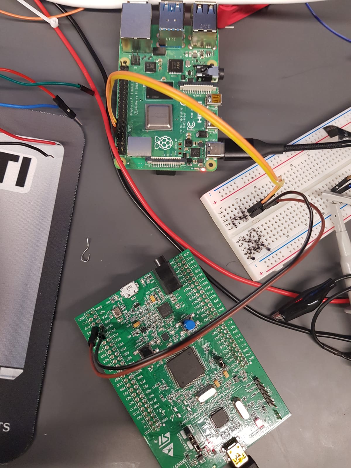
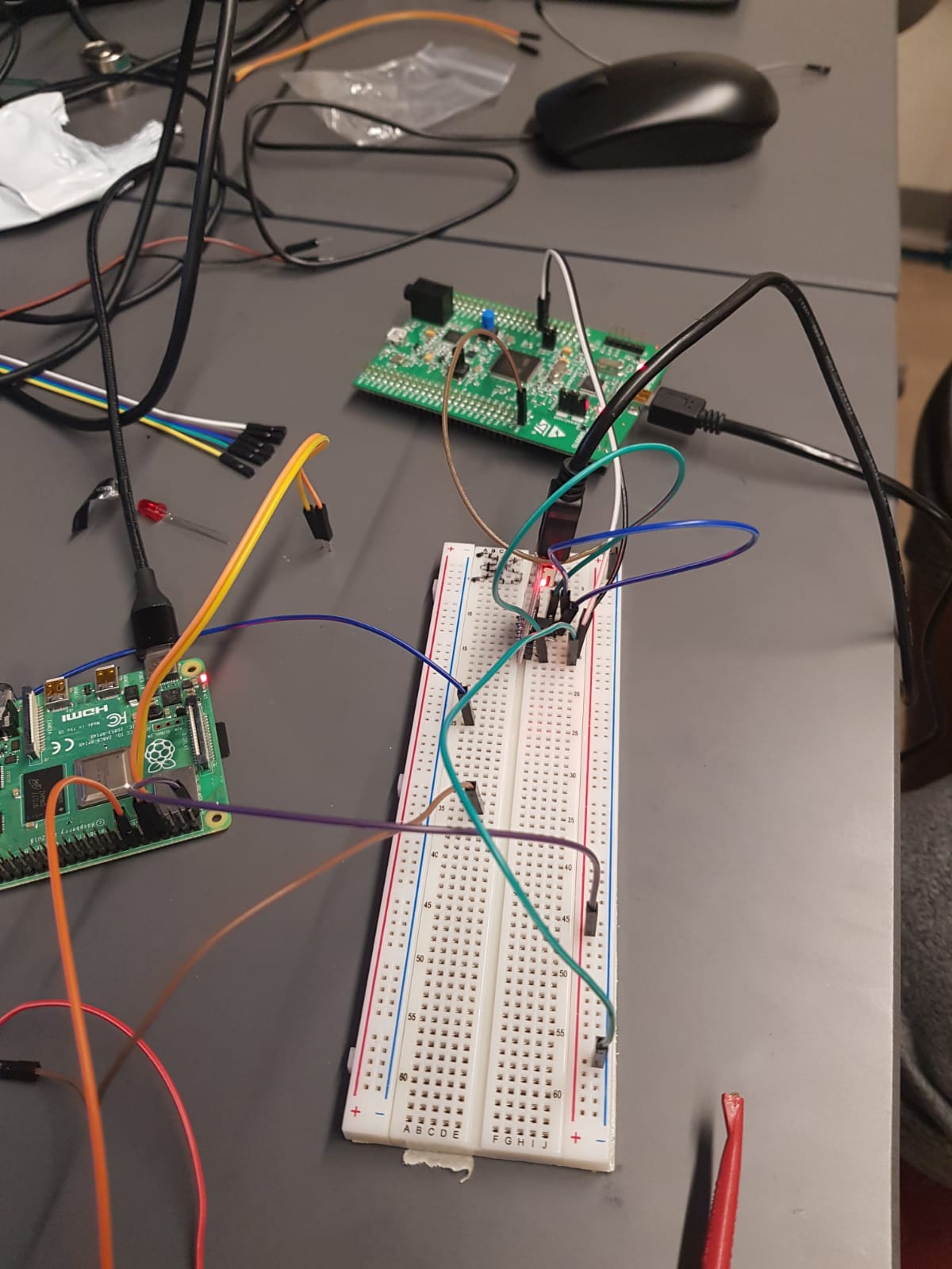
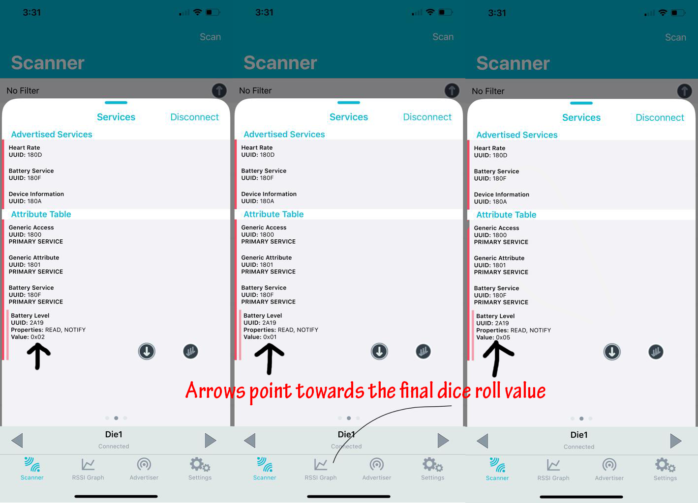
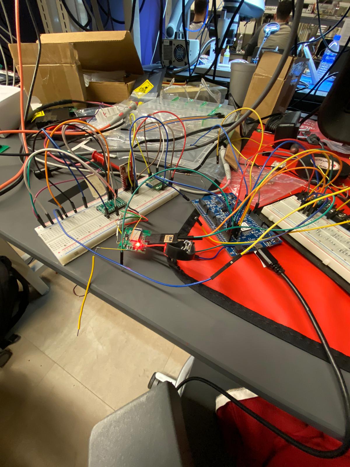
This week, after Carson soldered all the components onto the die PCB, I tried testing the code I wrote for the breakout board to be able to get the orientation data and transmit over bluetooth. I had to make some changes to the original code to use different pins for SPI and use the internal clock instead of the external oscillator circuit that was on the nRF52832 breakout board. I got the Bluetooth part of it fairly quickly and was able to pick up the BLE advertisement from the MDBT42 on the PCB. The IMU however did not initialize at all. So, I built a test circuit to use the IMU from the breakout board that we had, while processing from the microcontroller on the PCB (as shown in the image). This also led to no results and we weren't able to send any data over SPI. After this continued for a couple days with different kinds of oscilloscope testing, we figured out that the issue was a short between SCL and SDI. Todd and Carson reflowed the solder around the IMU to fix that which then allowed me to flash code onto the die PCB and successfully send over orientation data! The image with the red text shows different rolls that was captured on a BLE scanner app. We thus have a complete die subsystem.
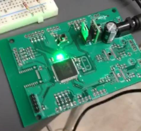
I then moved on to write some code to do some initial testing of the main PCB. I wrote a blinking LED program for the STM32F4 to test the main PCB and that worked as well, as shown by the image.
Week 12
Due Date: 11/08/2019
Total Hours: 8 hours
Description of Design Efforts:
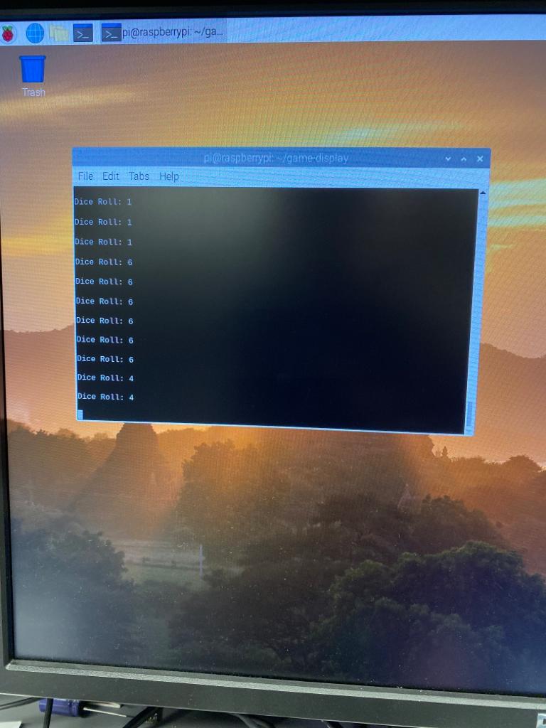
This week I worked primarily to write some firmware code for the STM32F4. Carson soldered the RN4020 to the PCB, so I wrote some code to test the UART communication with the microcontroller. I was able to get the STM32F4 to talk to both the Raspberry Pi and RN4020. Furthermore, I wrote code to interface with the die that we had completed last week and was able to receive the dice roll information as shown in the attached image. This also helped us check off a PSSC to communicate a die roll to the microcontroller wirelessly.
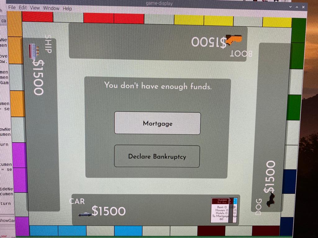
I then worked on upgrades to the game software and implemented a dialog box with buttons as shown in the image. It currently cannot take input, but adding a connection to that should be relatively simple. I hope to get a basic game state machine programmed in by next week.
.jpeg)
Week 13
Due Date: 11/16/2019
Total Hours: 10 hours
Description of Design Efforts:
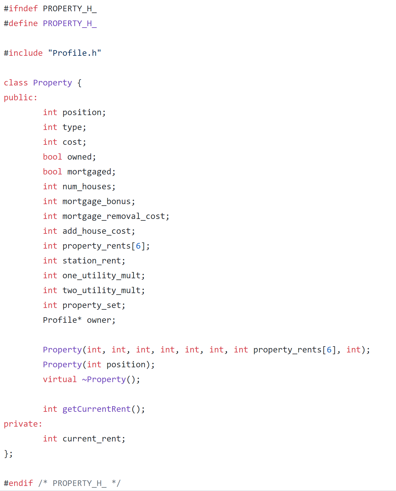
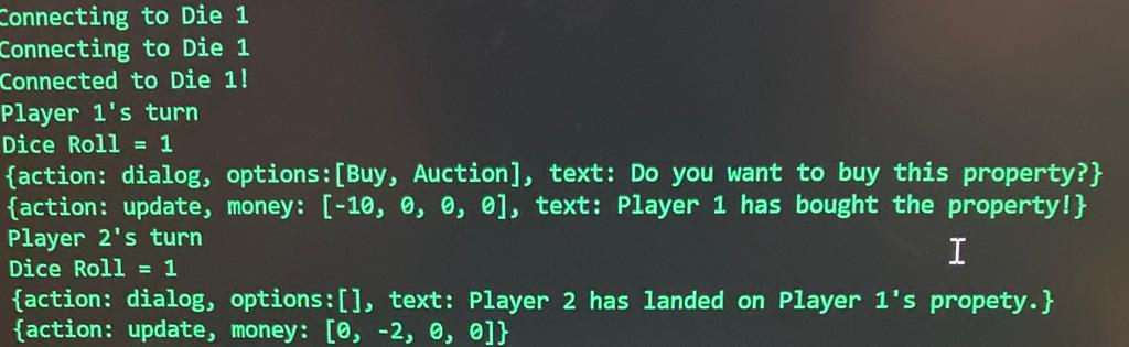
This week I primarily worked on the firmware side of the STM32F4 to get started on the gameplay logic. I set up the required data structures for properties and player profiles and programmed the state machine for property interactions. As shown in the first image, I was able to simulate two players playing where the first lands on a property, buys it and the second lands on the same property and has to pay rent to the first player. Since our Raspberry Pi ran into some issues where it didn't accept any UART communication, the output shown is from a FTDI USB-Serial chip that I plugged into my machine to visually see the output. The goals for next week are to implement the chance and community chest cards, as well as piece movement.
I also ran some initial tests with the electromagnet after Alex built the full enclosure. Since the acrylic panel is thick, the electromagnet (which has a force limit of 25N) was not able to fully move even a small nut around (size comparison shown in the image where the shadow underneath is the electromagnet). I then tried it with some passive magnets and found that they worked a little better. Thus, our solution for the game pieces will be to embed small magnets at their base so that it can easily be caught by the electromagnet.